High performance, low cost microelectronic circuit package with interposer

Inactive Publication Date: 2005-05-03
INTEL CORP
View PDF62 Cites 139 Cited by
  • Summary
  • Abstract
  • Description
  • Claims
  • Application Information

AI Technical Summary

Problems solved by technology

Typically, in a high volume manufacturing environment, cost w

Method used


Image

  • High performance, low cost microelectronic circuit package with interposer
  • High performance, low cost microelectronic circuit package with interposer
  • High performance, low cost microelectronic circuit package with interposer

Examples


Embodiment Construction

[0012]In the following detailed description, reference is made to the accompanying drawings that show, by way of illustration, specific embodiments in which the invention may be practiced. These embodiments are described in sufficient detail to enable those skilled in the art to practice the invention. It is to be understood that the various embodiments of the invention, although different, are not necessarily mutually exclusive. For example, a particular feature, structure, or characteristic described herein in connection with one embodiment may be implemented within other embodiments without departing from the spirit and scope of the invention. In addition, it is to be understood that the location or arrangement of individual elements within each disclosed embodiment may be modified without departing from the spirit and scope of the invention. The following detailed description is, therefore, not to be taken in a limiting sense, and the scope of the present invention is defined on...


PUM


Abstract

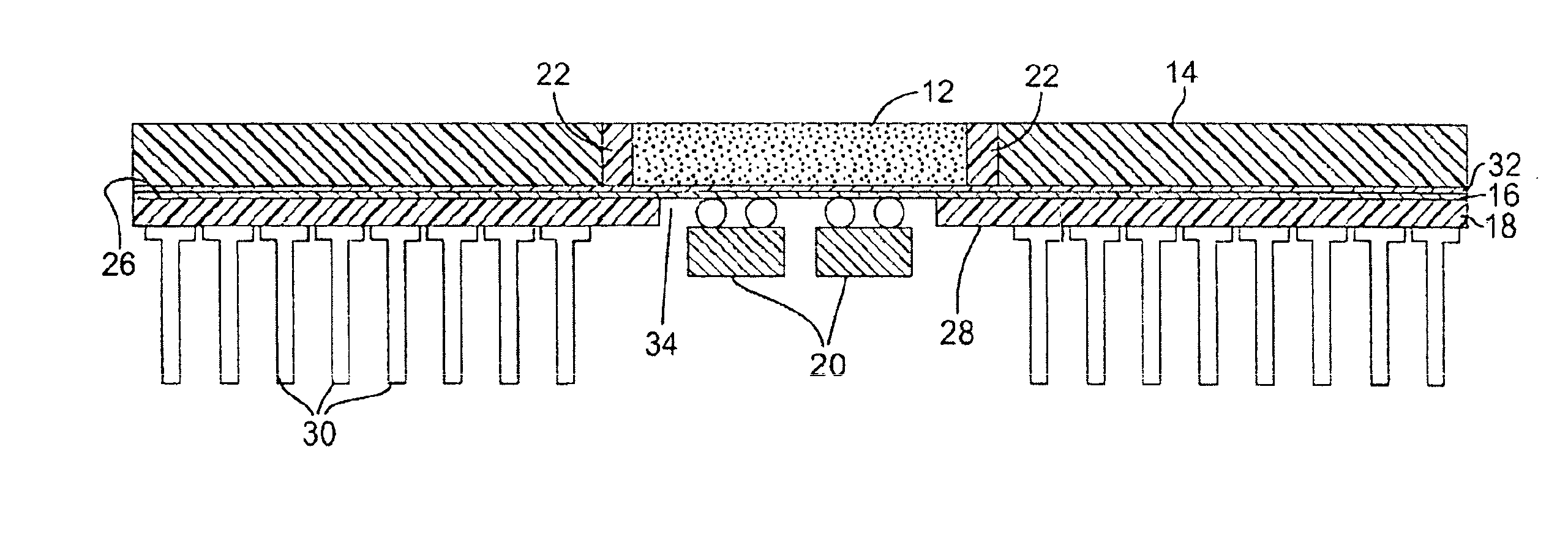
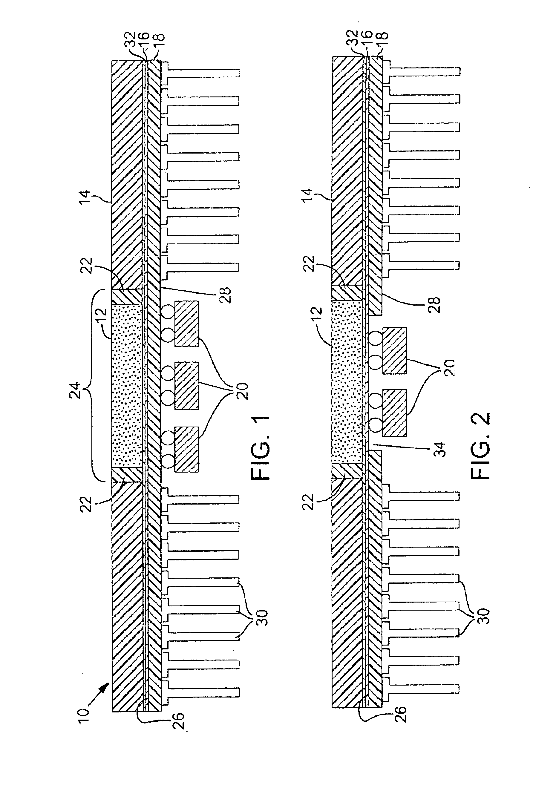
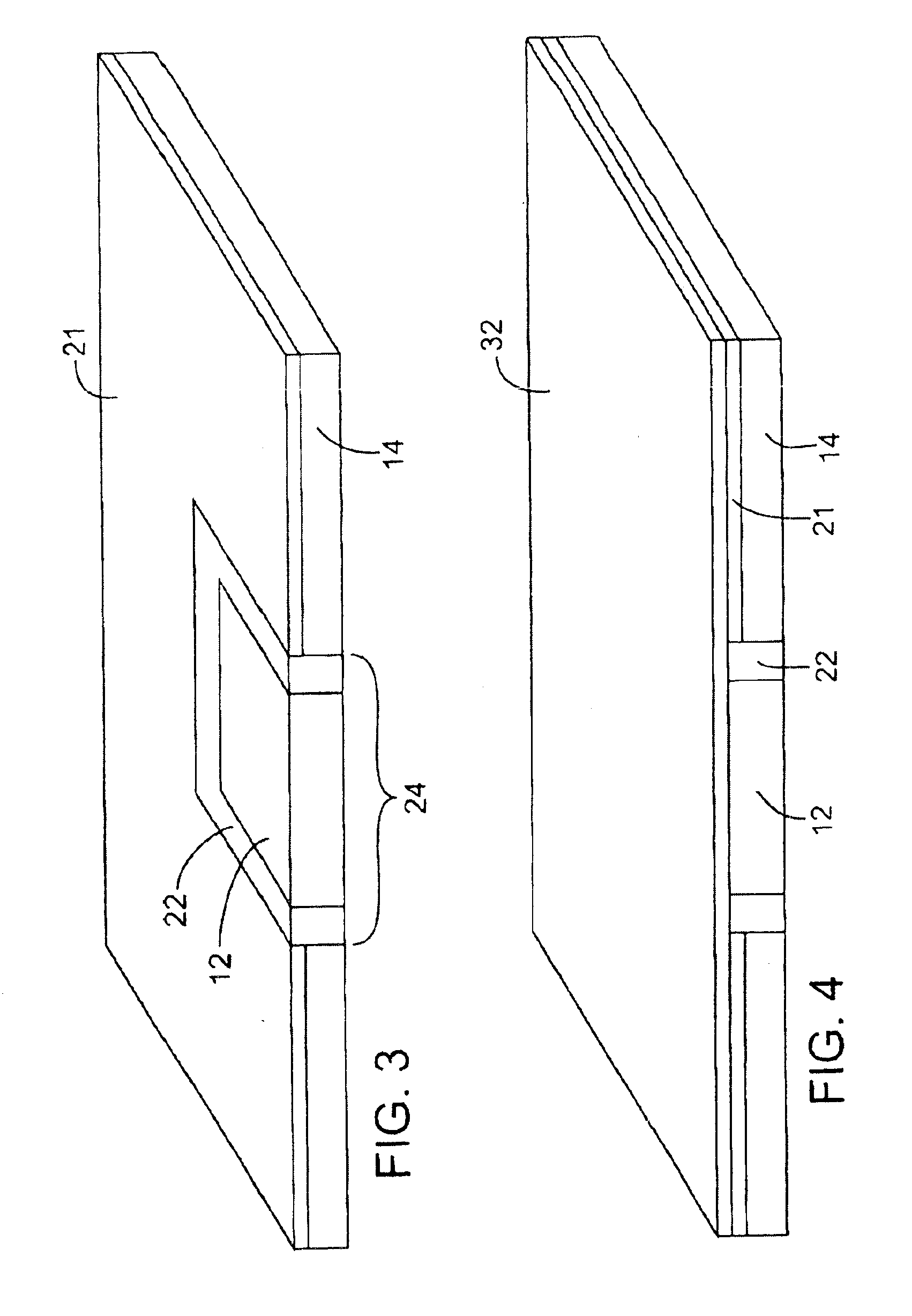
A low cost technique for packaging microelectronic circuit chips fixes a die within an opening in a package core. At least one metallic build up layer is then formed on the die/core assembly and a grid array interposer unit is laminated to the build up layer. The grid array interposer unit can then be mounted within an external circuit using any of a plurality of mounting technologies (e.g., ball grid array (BGA), land grid array (LGA), pin grid array (PGA), surface mount technology (SMT), and/or others). In one embodiment, a single build up layer is formed on the die/core assembly before lamination of the interposer.

Description

FIELD OF THE INVENTION[0001]The invention relates generally to microelectronic circuits and, more particularly, to structures and techniques for packaging such circuits.BACKGROUND OF THE INVENTION[0002]After a microelectronic circuit chip (i.e., a die) has been manufactured, the chip is typically packaged before it is sold to the public. The package provides both protection for the chip and a convenient and often standardized method for mounting the chip within an external system. The circuit package must include some means for providing electrical communication between the various terminals of the circuit chip and the exterior environment. Many different packaging technologies have been used in the past for providing this communication. The type of package that is used for a particular chip can have a significant impact on the performance of the completed device. Typically, in a high volume manufacturing environment, cost will be a primary concern in selecting a packaging technolog...

Claims


Application Information

Patent Timeline
IPC IPC(8): H01L23/13H01L23/58H01L23/64H01L23/16H01L23/12H01L23/24H01L23/48H01L23/498H01L25/00
CPCH01L23/13H01L23/24H01L23/49838H01L23/642H01L2224/16H01L2924/01079Y10S257/924H01L2924/15312H01L2924/1532H01L2924/19106H01L2924/3011H01L2924/01019H01L2924/15173H01L23/498
Inventor TOWLE, STEVENTANG, JOHNVANDENTOP, GILROY
Owner INTEL CORP
Why Eureka
Try Eureka