
Method, apparatus, and medium for calibration of tomosynthesis system geometry using fiducial markers with non-determined position

a technology of tomosynthesis system and calibration method, which is applied in the field of methods, apparatuses and media for calibration of tomosynthesis system geometry using fiducial markers with non-determined positions, can solve the problems of inability to carry over other conventional methods to determining tomosynthesis system geometry, inability to image a patient, and inability to achieve the effect of ensuring the quality of reconstructed images

Active Publication Date: 2005-05-03
GENERAL ELECTRIC CO
View PDF3 Cites 58 Cited by
  • Summary
  • Abstract
  • Description
  • Claims
  • Application Information

AI Technical Summary

Benefits of technology

[0009]In addition, the present invention uses a phantom including fiducial markers to determine tomosynthesis system geometry. The used phantom does not need to be a rigid structure, but it can comprise fiducial markers which are physically separate from each other and that remain stationary during the image acquisition process. Use of a non-rigid structure as the phantom (or even separate markers, that are not mechanically connected with each other) allows for simultaneous imaging of an object.
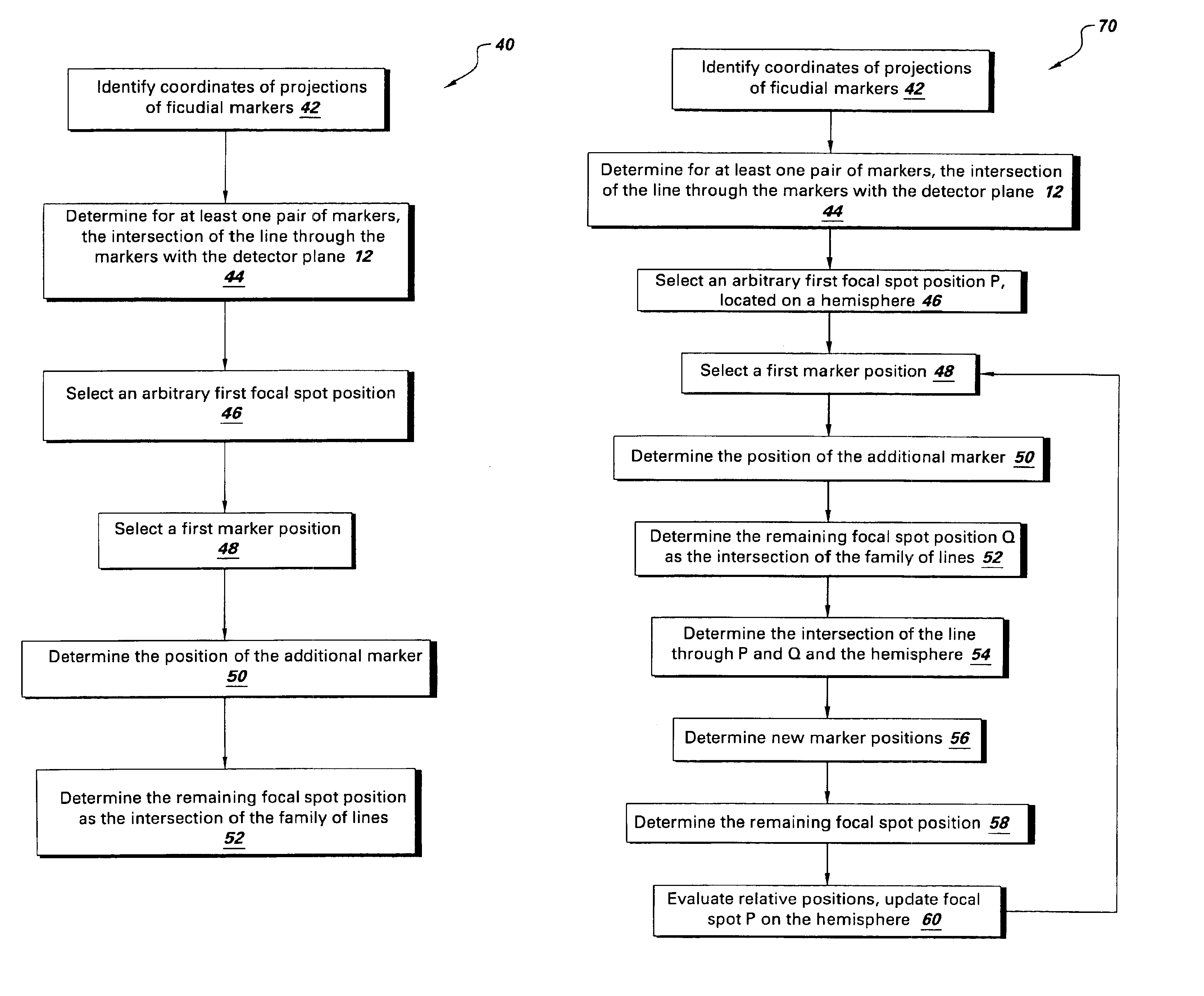
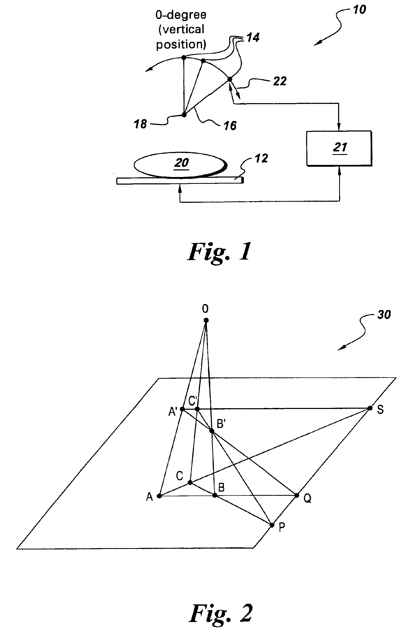
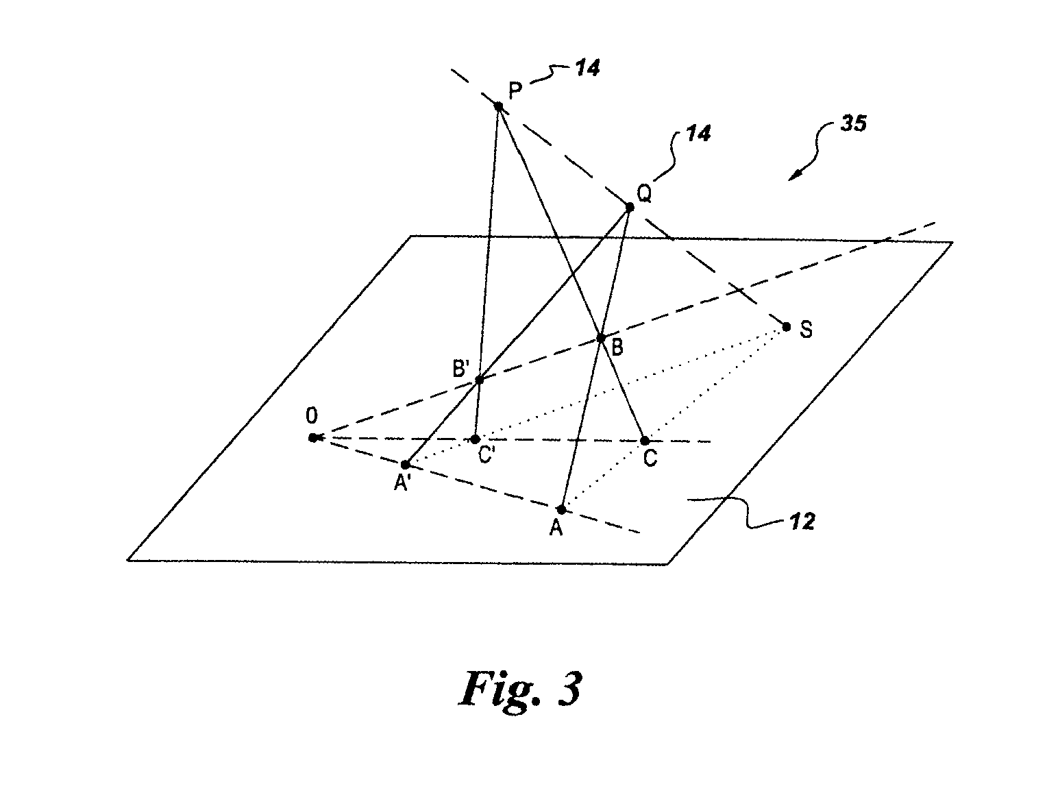
[0014]More particularly, the present invention uses a phantom with an almost arbitrary arrangement of fiducial markers, and does not require a special phantom with well-defined relative positions of the markers. Projection radiograph images of this phantom are acquired, and the positions of the projections of the markers in the images are assumed to be known (i.e., measurements of the locations of the shadows of the markers are assumed to be available). From this data set, a set of estimated focal spot locations as well as the associated estimated locations of the markers are derived such that optimal quality of the reconstructed images is guaranteed.

Problems solved by technology

This method requires a number of precise measurements and is typically complex, depending on the mechanical structure which connects the detector and the x-ray source.
Although conceptually similar to the problem of determining the tomosynthesis system geometry from images of some object, these other conventional methods cannot be carried over to determining tomosynthesis system geometry because a tomosynthesis system includes a different system geometry for each acquired image, typically because of a change in the x-ray source (and thus focal spot) location for each acquired image.
However, these approaches are based upon the use of a well-defined phantom (which is relatively expensive), and usually cannot be used while imaging a patient.
Consequently, the imaging procedure has to be repeated if the CT system geometry was not well calibrated during the patient image acquisition.

Method used


Image

  • Method, apparatus, and medium for calibration of tomosynthesis system geometry using fiducial markers with non-determined position
  • Method, apparatus, and medium for calibration of tomosynthesis system geometry using fiducial markers with non-determined position
  • Method, apparatus, and medium for calibration of tomosynthesis system geometry using fiducial markers with non-determined position

Examples


Embodiment Construction

[0023]As used herein, the terms “adapted to”, “configured to” and the like refer to the components that are arranged to provide a desired function as might be know to one skilled in the art. For example, in the situation of the processing of signals, data and the like, the term “adapted to” refers to a component such as, for example, a preprogrammed digital computer, an application-specific integrated circuit (ASIC), or other electronic, analog or optical computing device that can be prepared to process input signals in accordance with a desired algorithm to provide a desired output signal. In the situation of a mechanical or electromechanical device, the term “adapted to” refers to the components, for example, being assembled, connected or disposed in an operational relationship so as to provide a desired functionality, make up or arrangement in a device.

[0024]Throughout the description of the present invention, reference is made to the x-ray source being “above the detector”, or a...


PUM


Abstract

Geometry of a tomosynthesis system including a detector and an x-ray source is determined using fiducial markers with non-determined positions. The geometry is determined by arbitrarily identifying at least two markers within an imaged volume, at different relative distances between the detector and the x-ray source, without having projections located on a straight line for all different source positions, and locating the projections of the markers within at least two images acquired of the imaged volume. The at least two images correspond to different positions of a focal spot of the x-ray source.

Description

BACKGROUND OF THE INVENTION[0001]In a typical tomosynthesis system, an x-ray source emits x-ray beams in the direction of an object to be imaged. These x-ray beams are subsequently detected by a detector, and are acquired by the tomosynthesis system.[0002]Further, in a typical tomosynthesis system, the imaged object remains in a fixed position, the x-ray source assumes different discrete positions along a trajectory in space. For each source position, a projection radiograph image is acquired.[0003]Once the images, included in the detected x-ray beams, of the object are acquired by the tomosynthesis system, reconstruction of three-dimensional structures of the imaged object from structures included in the acquired images is accomplished by the tomosynthesis system. Accurate and reliable reconstruction of 3-dimensional information about structures of the imaged object in tomosynthesis requires a precise knowledge of the tomosynthesis system geometry. The relative positions of the foc...

Claims


Application Information

Patent Timeline
Patent Type & Authority Patents(United States)
IPC IPC(8): A61B6/00G06T7/00
CPCA61B6/583G06T7/0042G06T7/0018G06T2207/30004G06T7/80G06T7/73
Inventor CLAUS, BERNHARD ERICH HERMANNOPSAHL-ONG, BEALEYAVUZ, MEHMET
Owner GENERAL ELECTRIC CO
Learn More