Real-time display of internal gyration angle in gyratory compaction material testing

a compaction material and real-time display technology, applied in the field of real-time display of internal gyration angle in gyratory compaction material testing, can solve the problems of inaccurate test, insufficient attention to features, and machines which do not maintain internal angles

Inactive Publication Date: 2005-05-10
PINE INSTR
View PDF5 Cites 15 Cited by
  • Summary
  • Abstract
  • Description
  • Claims
  • Application Information

AI Technical Summary

Benefits of technology

[0010]In accordance with another aspect of the invention, a gyratory compactor apparatus for subjecting a material to forces is provided which includes a system for determining and displaying an internal angle of gyration. In an alternate embodiment of the invention, a self-contained angle measurement instrument is placed into the compaction mold along with the asphalt mixture. The angle measurement instrument contains one or more sensors which measure the angle between a mold end plate (also referred to as a “mold plate”) and an interior of the mold cylinder. The measured internal gyration angle is then compared to a measured external mold cylinder angle (measured by sensing a position of an exterior of the mold cylinder), which is measured separately with respect to a secondary frame of reference. The difference between the readings is calculated and the result is applied to the mold cylinder measurement as an offset compensation factor. As the compactor operates, the mold cylinder angle is measured and the offset compensation factor is applied to determine the internal angle of gyration. The compensated internal angle measurement is displayed to the operator while the material is compacted. This alternate method of obtaining the internal gyration angle value from a self-contained, separate instrument and applying an offset compensation factor to the externally measured mold cylinder angle has the advantage of not requiring the use of any delicate measuring instruments inside the compaction mold under normal operating situations. Any of the measured angles or other data can be displayed separately or in combination in a display associated with a gyratory compactor.
[0012]An alternate method and system of the invention to obtain the internal angle of gyration is to instrument the gyratory compactor to directly measure at least one of the mold end plates with respect to a reference frame. The compactor is also instrumented with sensors to measure the mold cylinder angle with respect to the same reference frame. The internal angle and the external angle measurements are combined to yield the internal angle of gyration. This method has the advantage of directly measuring the mold end plate orientation during normal operation.
[0013]In accordance with another aspect of the invention, a gyratory compaction apparatus for subjecting a material to forces is provided which includes a method for determining the internal angle of a gyration compactor based on measurement of the external angle of gyration, and presenting said internal angle to the operator. Regardless of the various instrumentation or sensors used to measure the internal angle of gyration, the external angle can be measured in ways similar to existing designs where multiple sensors sense a position of the external mold wall and the angle of gyration is determined. The internal angle of gyration can be measured with multiple probes protruding through the ram heads and / or mold pucks or mold end plates to directly measure the position of the mold end plates during compaction. To reduce the sensitivity to debris, non-contact sensors may be employed in lieu of direct contact style. Angle data is displayed during operation of the gyratory compactor while the compaction is taking place. Angle data can also be printed or saved to a data file for later reference.

Problems solved by technology

Precise dynamic measurement of the gyration angle is critical to achieve accurate test results, and is complicated by the constant gyration / orbiting motion of the mold as material is compacted within it.
Measurement and display of the internal angle of gyration, vital to obtaining accurate tests results, is a feature not adequately addressed in the design of prior art gyratory compactors.
Machines which do not maintain the internal angle of gyration in operation produce inaccurate test results.
The instrument does not provide or display internal gyration angle data during the compaction test, which would allow a machine operator to immediately tell whether a particular test was being performed within the specified parameters.

Method used


Image

  • Real-time display of internal gyration angle in gyratory compaction material testing
  • Real-time display of internal gyration angle in gyratory compaction material testing
  • Real-time display of internal gyration angle in gyratory compaction material testing

Examples


Embodiment Construction

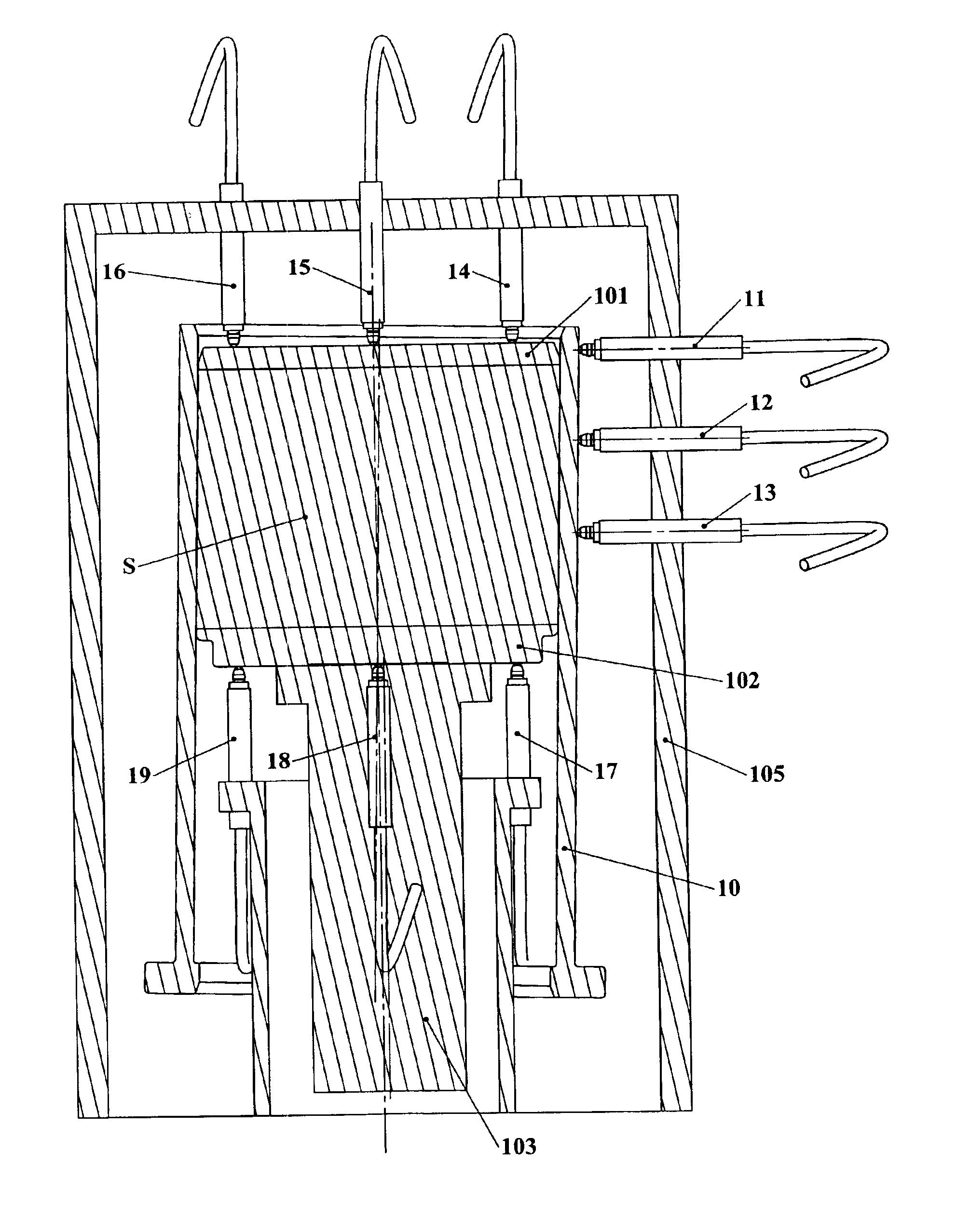
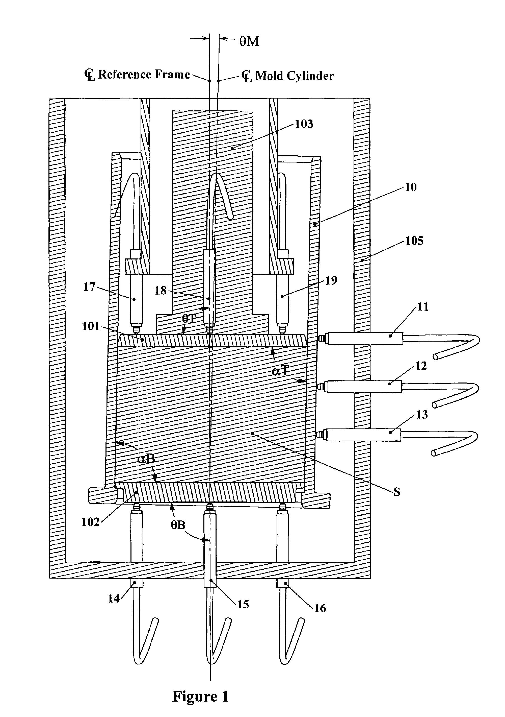
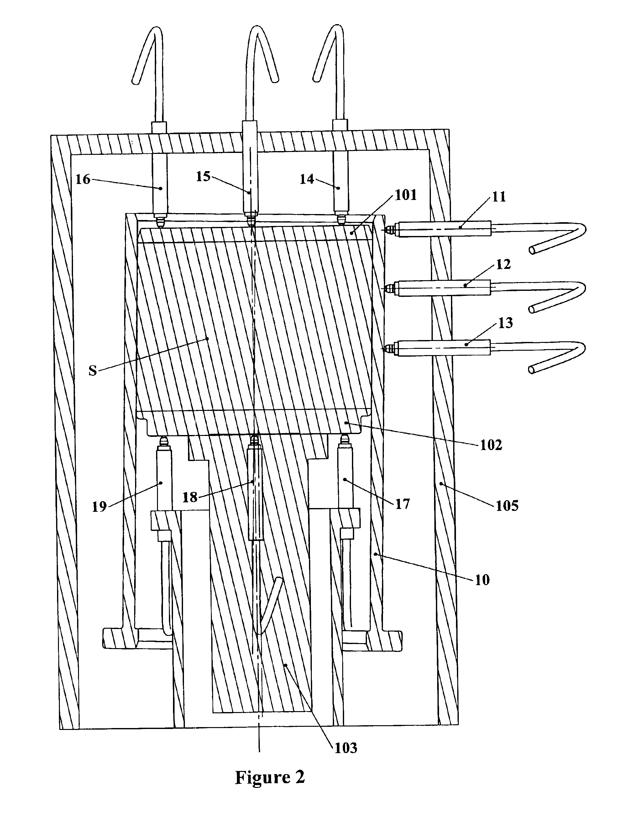
[0020]FIG. 1 illustrates a mold cylinder 10 of the type commonly used in a gyratory compactor. Within the mold cylinder 10 is positioned a first mold plate 101 and a second mold plate 102, between which a material specimen S such as HMA is placed and compacted by a compaction ram 103 which passes through one end of the mold. A gyratory compactor machine typically has a frame 105 for, among other things, supporting the mold in a generally vertical orientation, a gyration mechanism which engages or moves the mold to gyrate it about its axis, i.e., to move one end of an axis of the mold cylinder in a circle while the opposite end of the axis is held substantially at one point; and a ram 103 (also referred to as a “compaction ram”) which is advanced or driven through one of the ends of the mold cylinder 10 against one of the mold end plates 101 or 102 (as shown, against mold plate 101). Alternatively, the ram 103 may have a material contacting surface which contacts the material specime...


PUM

PropertyMeasurementUnit
mold gyration angleaaaaaaaaaa
internal angle of gyrationaaaaaaaaaa
angle of gyrationaaaaaaaaaa

Abstract

A gyratory compacting apparatus and data capture and display system for compacting a specimen of material within a mold as the mold is gyrated, and capturing and displaying data on an internal angle of gyration during mold gyration, the apparatus and system having a generally cylindrical mold for holding a specimen of material to be compacted, at least one plate in the mold in contact with material in the mold and which moves relative to the mold as the mold is gyrated, and at least one sensor which measures an internal angle of gyration between the mold and a mold plate and captures internal gyration angle data for real-time display of internal gyration angle data during gyration and compaction. Alternative arrays of internal gyration angle sensors are disclosed.

Description

[0001]This application claims the benefit of Provisional Application No. 60 / 346,068, filed Oct. 19, 2001.FIELD OF THE INVENTION[0002]The present invention relates generally to a method and apparatus for testing materials and, in particular, to a method and apparatus for testing materials by simultaneous compaction and gyration, and real-time collection and presentation, transfer or display of data from such tests.BACKGROUND OF THE INVENTION[0003]Gyratory compactors are used to test material properties, such as hot-mix asphalt (HMA) mixture specimens in the laboratory to assess and predict paving material performance. For HMA testing, Federal Highway Administration (FHWA) guidelines and test procedures require in essence that an asphalt material sample be gyrated within a mold while undergoing compaction, to simulate the effect of road traffic. The extent of compaction according to the testing procedures is controlled by the force applied to a compaction ram, the angle of gyration or...

Claims


Application Information

Patent Timeline
Patent Type & Authority Patents(United States)
IPC IPC(8): B29C43/04B29C43/58G01N3/08G01N1/28B29C43/36
CPCB29C43/04G01N3/08G01N1/286B29C43/58B29C43/361B29C2043/043
Inventor HINES, THEODORE G.
Owner PINE INSTR
Why Eureka
Try Eureka