Flow rate control apparatus

Inactive Publication Date: 2005-05-10
SMC CORP
View PDF18 Cites 34 Cited by
  • Summary
  • Abstract
  • Description
  • Claims
  • Application Information

AI Technical Summary

Benefits of technology

[0014]A general object of the present invention is to provide a flow rate control apparatus which makes it possible to eliminate any delay

Problems solved by technology

Therefore, some dispersion appears in the flow rate due to the delay of response when the valve opening degree of the unillustrated valve plug is controlled, and it is difficult to stably control the flow

Method used


Image

  • Flow rate control apparatus
  • Flow rate control apparatus
  • Flow rate control apparatus

Examples


Embodiment Construction

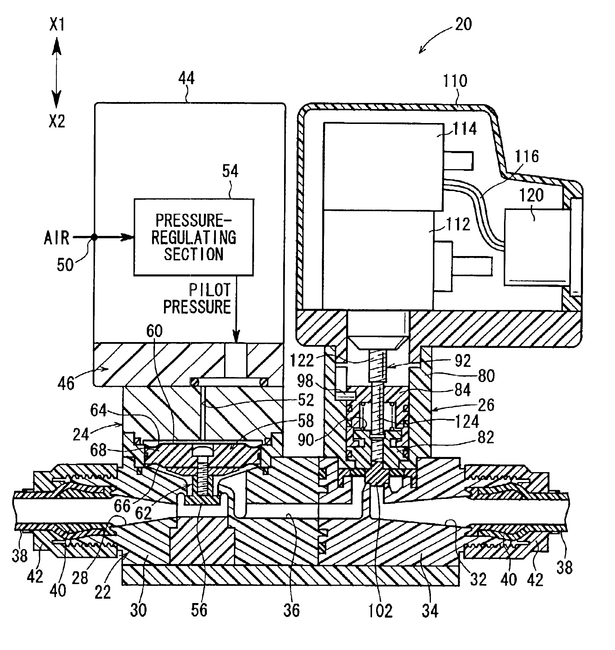
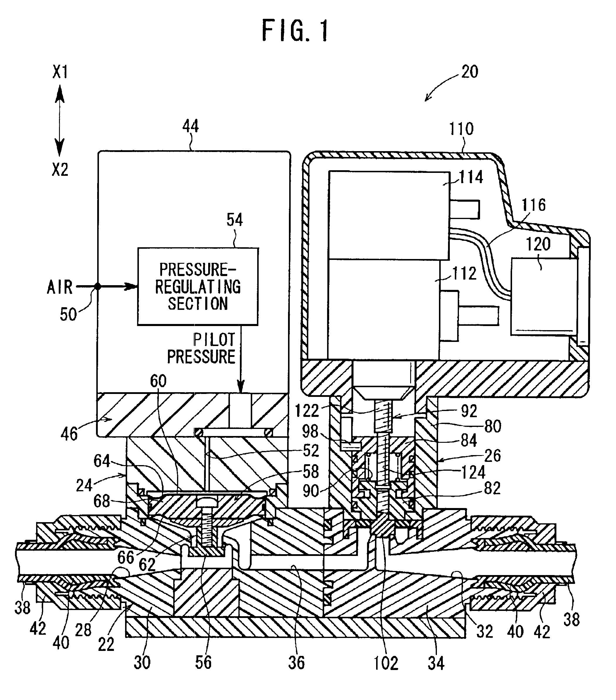
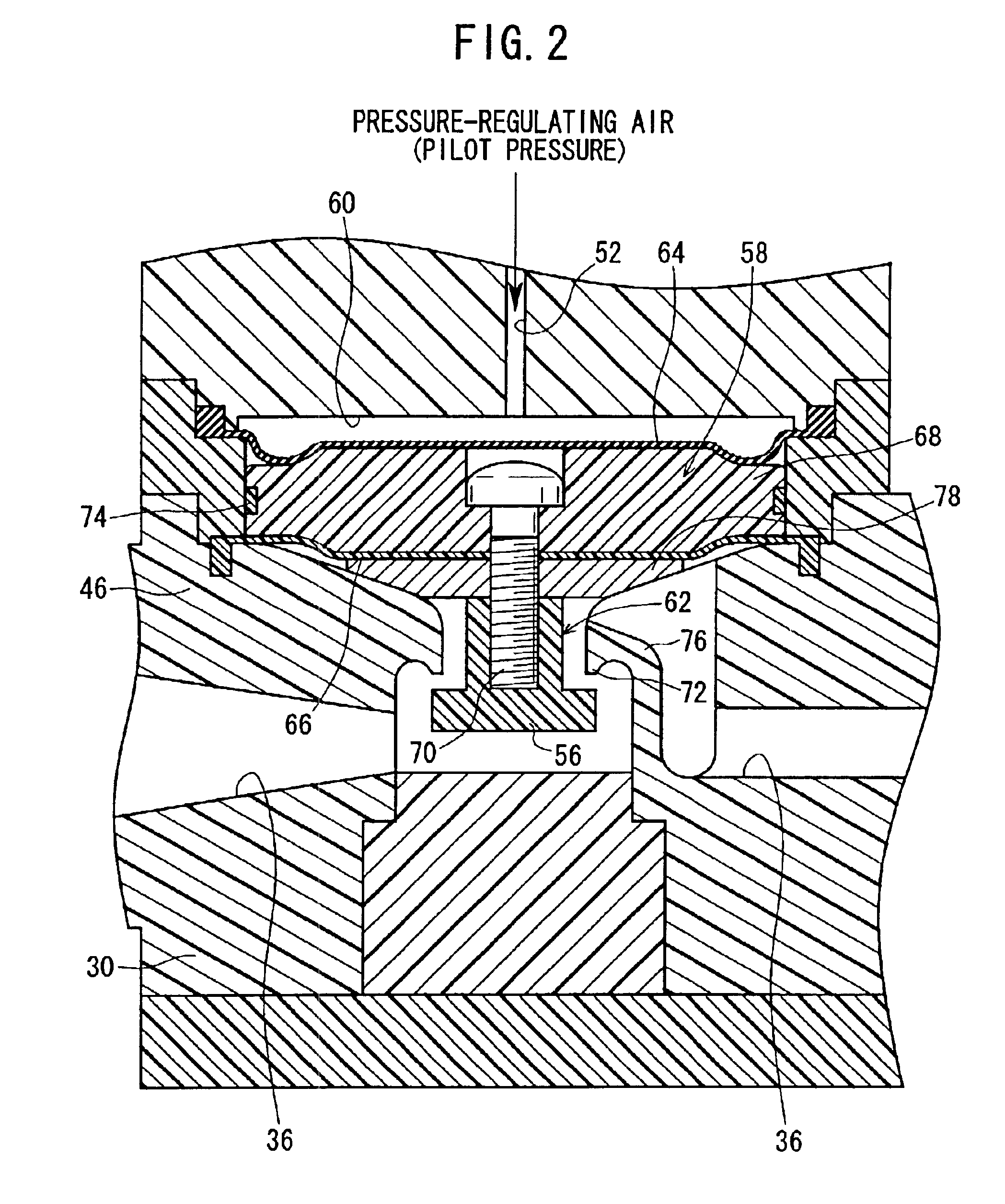
[0027]In FIG. 1, reference numeral 20 indicates a flow rate control apparatus according to an embodiment of the present invention.

[0028]The flow rate control apparatus 20 comprises a joint section 22 to which unillustrated tubes are detachably connected while being spaced from each other by a predetermined distance, a pulsation-attenuating mechanism 24 which is provided on one side in the axial direction of the joint section 22, and a flow rate control mechanism 26 which is provided on the other side in the axial direction of the joint section 22.

[0029]The flow rate control apparatus 20 is constructed by integrally assembling the joint section 22, the pulsation-attenuating mechanism 24, and the flow rate control mechanism 26.

[0030]The joint section 22 has a first joint body 30 which is provided with a first port 28 at one end, and a second joint body 34 which is provided with a second port 32 at the other end. A fluid passage 36 is provided in the first and second joint bodies 30, 3...


PUM


Abstract

A flow rate control apparatus is constructed by integrally assembling a pulsation-attenuating mechanism for balancing a regulated pilot pressure from a pressure-regulating section and a primary pressure of a pressure fluid flowing through a fluid passage to attenuate pressure fluctuation caused by pulsation of the pressure fluid, and a flow rate control mechanism for controlling a flow amount of the pressure fluid flowing through the fluid passage by adjusting a valve lift amount of a valve plug with a linear actuator controlled based on a rotary driving control signal from a controller.

Description

BACKGROUND OF THE INVENTION[0001]1. Field of the Invention[0002]The present invention relates to a flow rate control apparatus which attenuates the pulsation of a pressure fluid flowing through a fluid passage and which is capable of controlling the flow rate of the pressure fluid highly accurately.[0003]2. Description of the Related Art[0004]FIG. 10 shows a conventional flow rate control system for controlling the flow rate of a fluid flowing through a fluid passage.[0005]The flow rate control system 1 comprises a pump 3 which pumps and feeds a pressure fluid stored in a tank 2, an opening / closing valve 5 which is connected on the downstream side of the pump 3 via a tube passage 4 and which opens / closes a fluid passage for the pressure fluid fed from the pump 3, and a flow rate control valve 7 which is connected on the downstream side of the opening / closing valve 5 via a tube passage 6 and which controls the flow rate of the pressure fluid flowing through the fluid passage.[0006]A ...

Claims


Application Information

Patent Timeline
IPC IPC(8): G05D7/06G05D7/00G05D7/03G05D16/18
CPCG05D16/185G05D7/0635G05D7/005Y10T137/7761Y10T137/7782Y10T137/8242Y10T137/87917G05D7/00
Inventor FUKANO, YOSHIHIROUCHINO, TADASHISUZUKI, TAKAMITSU
Owner SMC CORP
Why Eureka
Try Eureka