Data input method for a holographic digital data storage system

a data storage system and data input technology, applied in optical recording/reproducing/erasing methods, instruments, electromagnetic radiation sensing, etc., can solve the problems of difficult to distinguish between an “on an “off” state of pixel during the reproduction process of input data, and achieve the effect of reducing the reproduction errors of holographically stored digital data

Inactive Publication Date: 2005-05-10
WI LAN INC
View PDF18 Cites 25 Cited by
  • Summary
  • Abstract
  • Description
  • Claims
  • Application Information

AI Technical Summary

Benefits of technology

[0015]It is, therefore, an object of the present invention to provide a data input method capable of reducing reproduction errors of holographically stored digital data.

Problems solved by technology

However, the conventional data arranging scheme described above suffers from certain drawbacks in that it is difficult to distinguish an “ON” state of pixel from an “OFF” state of pixel during the reproduction of the input data.
Therefore, even a sequence of data consecutively written on a single column or row of a page can experience a large intensity variation in its “ON” pixel values (corresponding to binary “1” of the input data), rendering it difficult to identify an “ON” pixel and an “OFF” pixel in the reproduction process of the data.

Method used


Image

  • Data input method for a holographic digital data storage system
  • Data input method for a holographic digital data storage system
  • Data input method for a holographic digital data storage system

Examples


Embodiment Construction

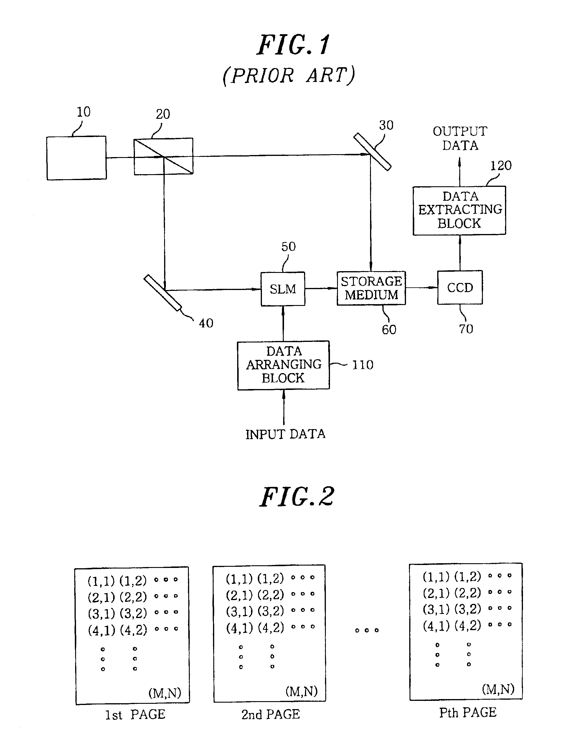
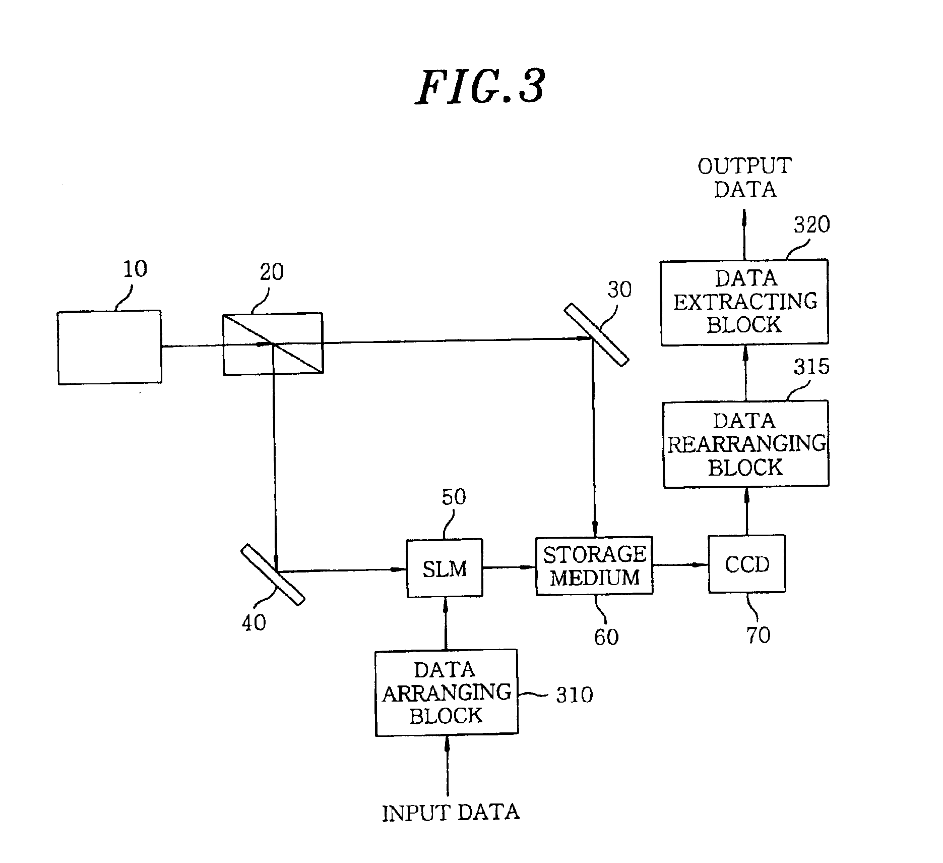
[0021]FIG. 3 shows a schematic view of a holographic digital storage system in accordance with an embodiment of the present invention, wherein like reference numerals are given for like parts as those of the prior art holographic digital data storage system shown in FIG. 1.

[0022]As shown in FIG. 3, the holographic digital data storage system includes a light source 10, a beam splitter 20, a first and a second mirror 30 and 40, an SLM 50, a storage medium 60, a CCD 70, a data arranging block 310, a data rearranging block 315 and a data extracting block 320. The light source 10, the beam splitter 20, the mirrors 30, 40, the SLM 50, the storage medium 60, and the CCD 70 function in analogous manners to those of the prior art hologram digital data storage system of FIG. 1, and therefore descriptions on the operations thereof will not be repeated.

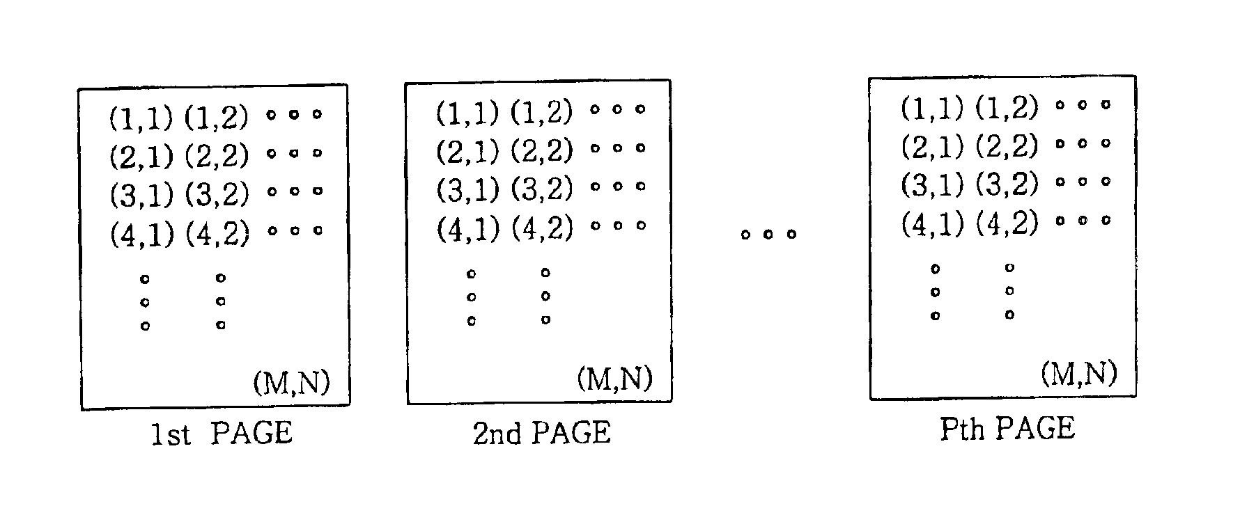
[0023]The data arranging block 310 arranges the sequential binary input data bits in a plurality of pages to be stored in the storage medium 60...


PUM

PropertyMeasurementUnit
timeaaaaaaaaaa
phaseaaaaaaaaaa
reflection angleaaaaaaaaaa

Abstract

A data input method is applied to a holographic digital data storage system in which sequential binary input data bits are arranged in an interleaved manner among pages. A first data bit is arranged in a specific position of a predetermined page, a second data bit is arranged in a specific position having similar beam intensity with that of the first data bit. Using this method, the holographic digital data storage system can be less affected by the adverse effect of spatial beam intensity variations and makes the entire data interleaved automatically to obtain more stable output data.

Description

FIELD OF THE INVENTION[0001]The present invention relates to a data input method; and, more particularly, to a data input method for a holographic digital data storage system, wherein hologram digital data are arranged in specific positions having similar beam intensity of each page in a storage medium.BACKGROUND OF THE INVENTION[0002]Recently, there have been reported increasing levels of research activities on holographic digital data storage systems triggered by the development of semiconductor lasers, e.g., charge coupled devices (CCDs) and the like. Since the holographic digital data storage system normally features a large storage capacity and a high data transfer rate, it has already been applied to, e.g., fingerprint recognition systems for storing and reproducing fingerprints and the scope of its applications keeps expanding.[0003]The holographic digital data storage system allows a signal beam transmitted from an object to interfere with a reference beam and writes thus ge...

Claims


Application Information

Patent Timeline
Patent Type & Authority Patents(United States)
IPC IPC(8): G11B7/0065G11B7/013G11C13/04G11B7/00G03H1/10G03H1/00G03H1/26G06K1/12
CPCG11B7/0065G11C13/042G11B7/013G03H1/00
Inventor ROH, JAE-WOO
Owner WI LAN INC
Why Eureka
Try Eureka