Hanger bar assembly

a technology of hanging rods and brackets, which is applied in the direction of machines/engines, liquid fuel engines, filing appliances, etc., can solve the problems of limiting the range of locations where fixtures may be placed, unable to direct joist connections, and not designed to support loads, etc., to achieve the effect of positive notice of proper engagement and the same cross-sectional profil

Inactive Publication Date: 2005-05-10
THOMAS & BETTS INT INC
View PDF57 Cites 91 Cited by
  • Summary
  • Abstract
  • Description
  • Claims
  • Application Information

AI Technical Summary

Benefits of technology

[0015]It is an advantage of the present invention to provide a hanger bar assembly for rigidly supporting an outlet box between spaced apart support elements.
[0016]It is a further advantage of the present invention to provide a hanger bar assembly including a pair of interlocking engageable channel members which may be adjusted to an operating length and clamped to prevent relative channel member movement.
[0017]It is still a further advantage of the present invention to provide a hanger bar assembly including a joist engaging device which provides an installer with positive notice of proper engagement.
[0018]In the efficient attainment of these and other objects the present invention provides a hanger bar assembly for supporting an outlet box between spaced apart support elements including a first channel member being longitudinally slidingly engagable with a second channel member forming a longitudinally adjustable support bar. A first channel member includes a plurality of longitudinally extending first grooves and a plurality of longitudinally extending first rails is provided. The second channel member includes a plurality of longitudinally extending second rails and a plurality of longitudinally extending second grooves. The first rails are slidingly received in said second grooves and the second rails being slidingly received in the first grooves such that lateral movement between the first and second channel members is resisted. A clamping device for urging the flanges into force engagement with the transverse extent of a corresponding channel member is also prov

Problems solved by technology

The ceiling covering material or sheathing is not designed to support loads perpendicular to its surfaces.
To achieve this, a fixture may be secured directly to a joist, however, this limits the range of locations where the fixture may be placed.
Such a limitation is problematic since it is often desirable to place the fixture in a specific position on the ceiling.
Therefore, if no joist is adjacently positioned to the desired location, direct joist connection is not possible.
Ceiling fans require high load bearing supports not only due to their weight but also due to the torque and vibrational forces that are generate by the rotation of the motor and fan blades.
Relatively small weight differences between the blades of a ceiling fan can produce rotational imbalances leading to large vibrational forces.
In such applications access to the joists is typically extremely limited.
The flanges, however, are relatively short thereb

Method used


Image

  • Hanger bar assembly
  • Hanger bar assembly
  • Hanger bar assembly

Examples


Embodiment Construction

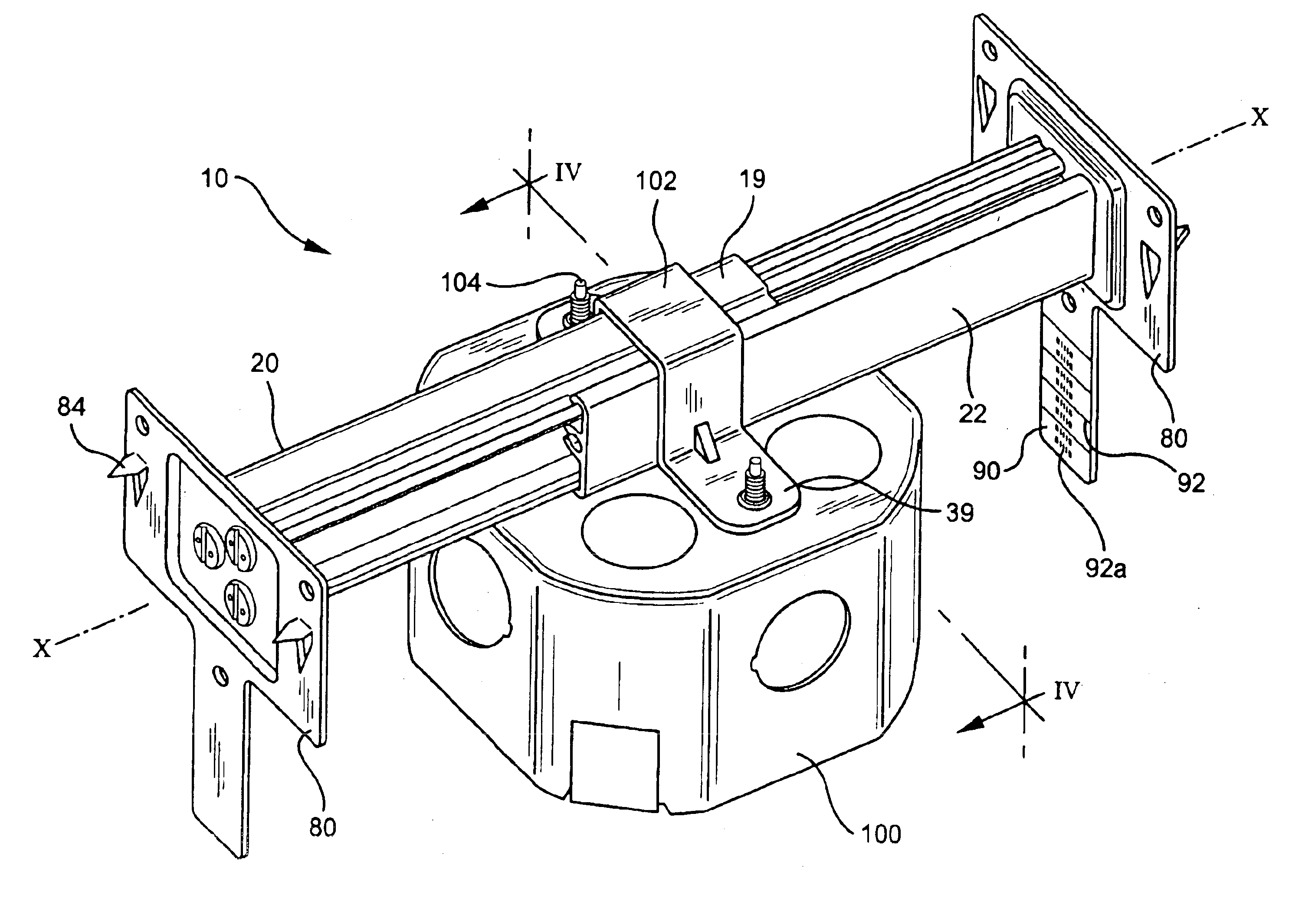
[0027]The hanger bar assembly of the present invention is adapted to support relatively heavy electrical fixtures such as ceiling fans in “new work” applications where the ceiling covering material such as plaster or drywall has yet to be installed and where the joists are substantially exposed. Ceiling fans, in addition to being relatively heavy, typically create cyclic loadings and vibrational forces due to the rotation of the motor and fan blades. Such forces must be adequately supported in order to ensure the fixture does not separate from the ceiling support structures to which it is attached. The hanger bar assembly of the present invention provides support for such fixtures as ceiling fans by maintaining its rigidity in configuration even under relatively high loadings.

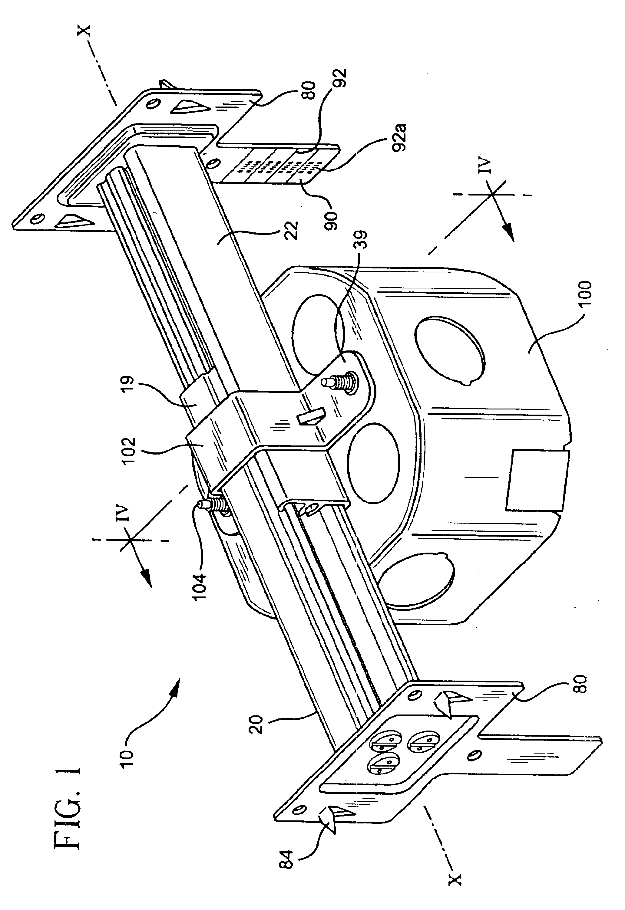
[0028]Referring to FIG. 1, the hanger bar assembly 10 formed in accordance with the preferred embodiment of the present invention is shown. Hanger bar assembly 10 includes a pair of channel members 20 and 22 an...


PUM


Abstract

A hanger bar assembly for supporting an outlet box between spaced apart support elements including a first channel member being longitudinally slidingly engagable with a second channel member forming a longitudinally adjustable support bar. The first channel member has a plurality of longitudinally extending grooves and the second channel member having a plurality of longitudinally extending rails slidingly received in the grooves such that lateral movement between the first and second channel members is resisted. A clamping device is provided for urging the first and second channel members into respective forced engagement thereby restricting movement between the first and second channel members. A securement device attached to the support bar for securing the support bar to the spaced support elements is further provided. The first and second channel members have apertures formed therein to accommodate fasteners for securing end plates to the support.

Description

FIELD OF INVENTION[0001]The present invention relates generally to a hanger bar assembly for supporting electrical fixtures. More particularly, the present invention relates to a hanger bar assembly having channel members that are slidably engagable, wherein longitudinal relative motion of the channel members is restricted upon securement of an electrical outlet box to the channel members.BACKGROUND OF THE INVENTION[0002]In order to secure electrical fixtures such as lights and fans in ceilings, a hanger bar device is typically employed. It is very important that a fixture be adequately supported in the ceiling since improper support could lead to the fixture breaking away from the ceiling. Ceilings are typically constructed of structural members including a series of spaced joists which are covered by lathe and plaster or a gypsum wallboard often referred to as drywall. The ceiling covering material or sheathing is not designed to support loads perpendicular to its surfaces. Theref...

Claims


Application Information

Patent Timeline
IPC IPC(8): F04D25/08F04D25/02F04D29/60B60N2/07
CPCB60N2/073F04D29/601F04D25/088Y10S248/906
Inventor DINH, CONG THANHGUPTA, HARSHDRANE, MARK R.
Owner THOMAS & BETTS INT INC
Why Eureka
Try Eureka