Recording head driving method, recording head, ink-jet printer

a driving method and recording head technology, applied in the direction of transmission systems, printing, instruments, etc., can solve the problems that the dispersion power is large, and the ink jet printer having the line head cannot adopt the recording method used in the serial head inkjet printers, etc., to achieve the effect of reducing the positional shift of dots

Inactive Publication Date: 2005-05-10
SONY CORP
View PDF14 Cites 12 Cited by
  • Summary
  • Abstract
  • Description
  • Claims
  • Application Information

AI Technical Summary

Benefits of technology

[0011]In view of the foregoing status of the art, it is an object of the present invention to provide a method for driving a recording head, a recording head, and an ink jet printer which enable reduction in the positional shift of dots on the recording medium and the instantaneous maximum dissipation power in time-division drive.

Problems solved by technology

Meanwhile, in carrying out multiple gray scale recording in the ink jet printer, the following two problems arise.
The first problem is that the ink jet printer having the line head cannot adopt the recording method used in the ink jet printer having the above-described serial head.
Thus, there arises a problem that the dissipation power tends to be larger than in the case of the serial head.
The second problem is that, in the ink jet printer having the line head, since the line head does not move in the main scanning direction, the respective lines print respective lines.
Moreover, the ink jet printer having the line head cannot adopt the recording method used in the ink jet printer having the serial head.
Therefore, the image quality is deteriorated by nonuniformity, a streak or the like due to the unevenness in the dot impact position on the paper.
Therefore, there arises a problem that a positional shift of dots occurs in the main scanning direction, causing deterioration in the image quality.

Method used


Image

  • Recording head driving method, recording head, ink-jet printer
  • Recording head driving method, recording head, ink-jet printer
  • Recording head driving method, recording head, ink-jet printer

Examples


first embodiment

[0078]FIG. 3 shows the overall structure of an ink jet printer 100 as a The ink jet printer 100 has a recording head having a PNM function to modulate the diameter of a dot by the number of ink droplets, using one or a plurality of ink droplets for forming one dot.

[0079]The ink jet printer 100 has a line head 120 having a recording range of substantially the same dimension as the page width of the paper P, a paper feed unit 130 for feeding the paper P into a predetermined direction, a paper charge unit 140 for supplying the paper P to the line head 120, a paper tray 150 for housing the paper P, and an electric circuit unit 160 for carrying out drive control of these units, which are provided inside a casing 110 constituting the appearance of the ink jet printer 100, as shown in FIGS. 3 and 4.

[0080]The casing 110 is formed, for example, in the shape of a rectangular parallelepiped. A paper discharge port 111 for discharging the paper P is provided on one lateral side of the lateral ...

second embodiment

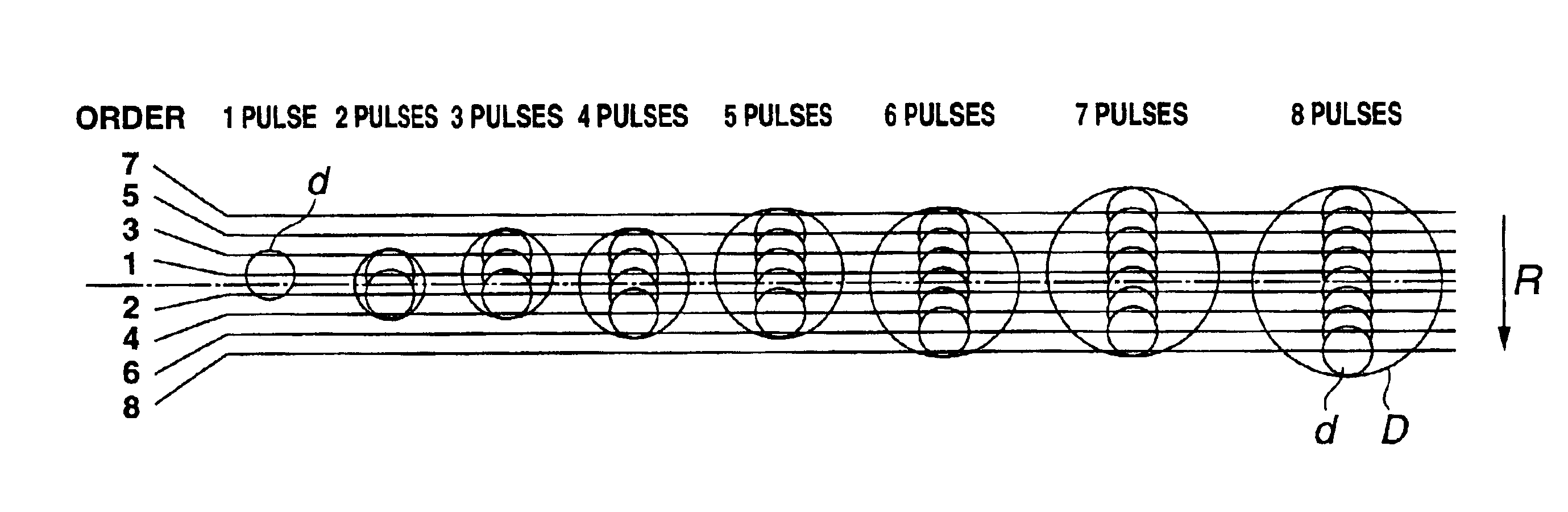
[0182]FIG. 30 shows an exemplary arrangement of dots to be recorded on the paper P by a method for driving the line head 120 provided in the ink jet printer 100 as the “PIT” in FIG. 30 represents the diameter of the dot D previously shown in FIG. 18 and is referred to as “pixel pitch” in this embodiment. Symbols “◯” in FIG. 30 correspond to the record data after correction and numbers provided in “◯” indicate the arrangement order of pulses to be objects of comparison with the record data from the comparators 163c. The positions of “◯” corresponding to the record data in FIG. 30 are coincident with the positions of dots within a pixel in printing, that is, the positions of the dots d formed by the respective ink droplets I shown in FIG. 18. In the line head 120, the arrangement of the record data relative to the center of image IC is changed depending on the pulse number is an even number or an odd number, in forming one dot in accordance with the PNM system.

[0183]Specifically, whe...


PUM


Abstract

An ink jet printer has a line head having heating elements (121d) for ejecting ink droplets from nozzles, in which the plurality of heating elements (121d) are arrayed in a direction substantially perpendicular to the paper feed direction. In the line head, the plurality of heating elements (121d) are divided into a plurality of blocks, with each block consisting of a predetermined number of spatially arrayed heating elements of the plurality of heating elements (121d) corresponding to the plurality of nozzles, and a phase signal PH is sequentially supplied to a set of heating elements (121d) simultaneously driven over the respective blocks, thus sequentially driving the respective heating elements (121d) by each set as a unit in a time-divisional manner. Thus, the ink jet printer can reduce the positional shift of dots on the paper and can reduce the instantaneous maximum dissipation power in time-division drive.

Description

TECHNICAL FIELD[0001]This invention relates to a method for driving a record heading, a record heading, and an ink jet printer for impacting ink droplets on a recording medium and thus recording dots made of the ink droplets on the recording medium.BACKGROUND ART[0002]A recording device of an ink jet system, that is, an ink jet printer, is a printer of a type which ejects ink droplets for recording from ejection ports of narrow nozzles arrayed on a record heading and impacts the ink droplets on a recording medium such as paper, thus recording characters or images in the form of dots. This ink jet printer is characterized by a high recording speed, a low recording cost and easy realization of color print. As the ink droplet ejection system in this ink jet printer, a thermal system using a heating element as an electrothermal conversion element is known.[0003]The printer of the thermal ink jet system has a recording head which has an ejection port for ejecting flying droplets (hereina...

Claims


Application Information

Patent Timeline
Patent Type & Authority Patents(United States)
IPC IPC(8): B41J2/05
CPCB41J2/04541B41J2/04543B41J2/04595B41J2/0458B41J2202/20
Inventor YAKURA, YUJIANDO, MAKOTOIKEMOTO, YUICHIRO
Owner SONY CORP
Why Eureka
Try Eureka