Method and apparatus for machining a workpiece, whereby chips are removed from the workpiece

Inactive Publication Date: 2005-05-10
DUERR ECOCLEAN GMBH
View PDF15 Cites 5 Cited by
  • Summary
  • Abstract
  • Description
  • Claims
  • Application Information

AI Technical Summary

Benefits of technology

[0026]It is particularly expedient to use a lubricant whose solidification point is higher than approximately 60° C., preferably higher than approximately 65° C. It is thereby ensured that the lubricant will solidify in the workpiece when cooled down to room temperatur

Problems solved by technology

This conventional lubrication and cooling of the machining tool by external supply of large amounts of liquid coolant has the disadvantage that complicated preparation and circulation systems are required for the large quantities of co

Method used


Image

  • Method and apparatus for machining a workpiece, whereby chips are removed from the workpiece
  • Method and apparatus for machining a workpiece, whereby chips are removed from the workpiece
  • Method and apparatus for machining a workpiece, whereby chips are removed from the workpiece

Examples


Example

[0057]Identical or functionally equivalent elements are designated by the same reference numerals in all Figures.

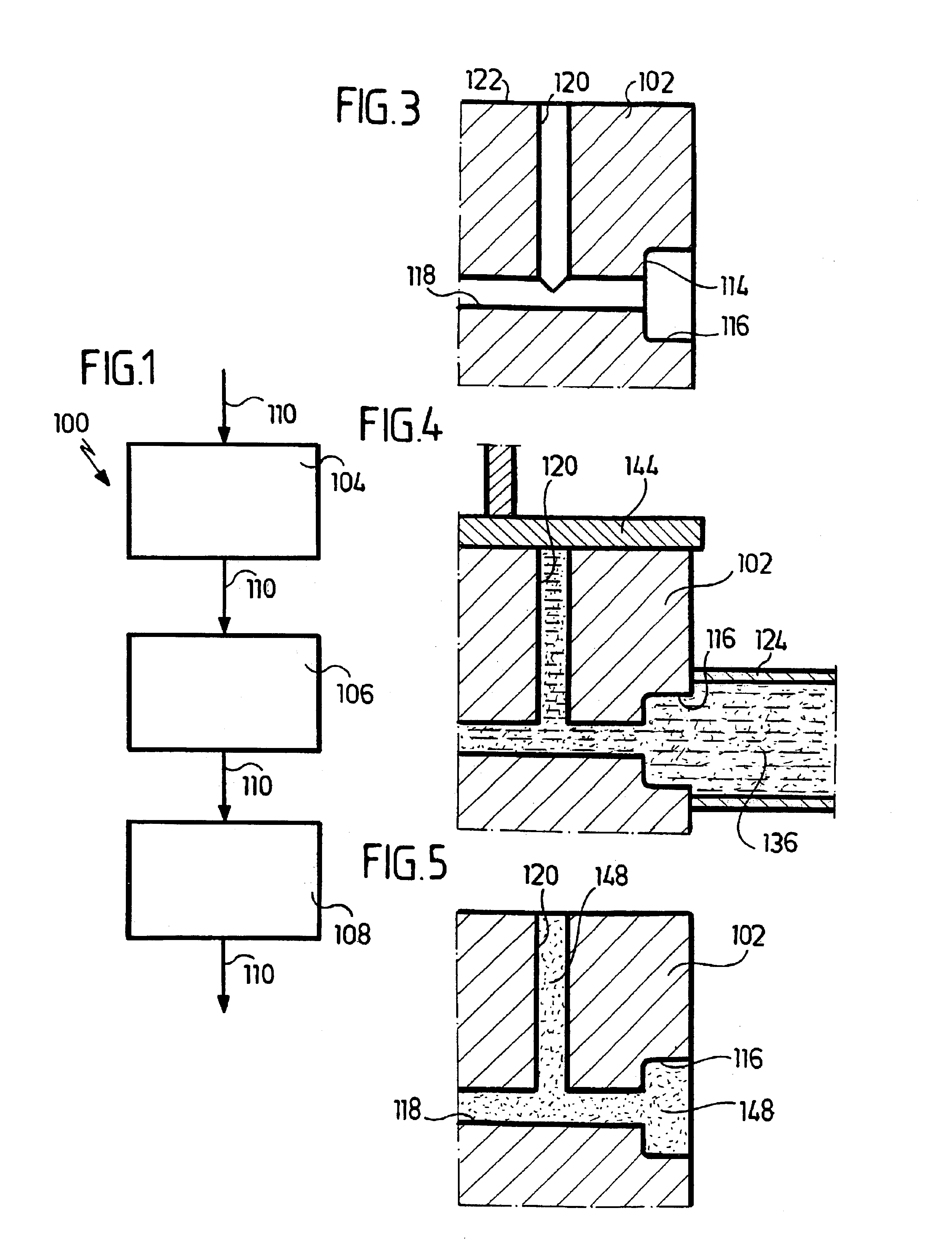
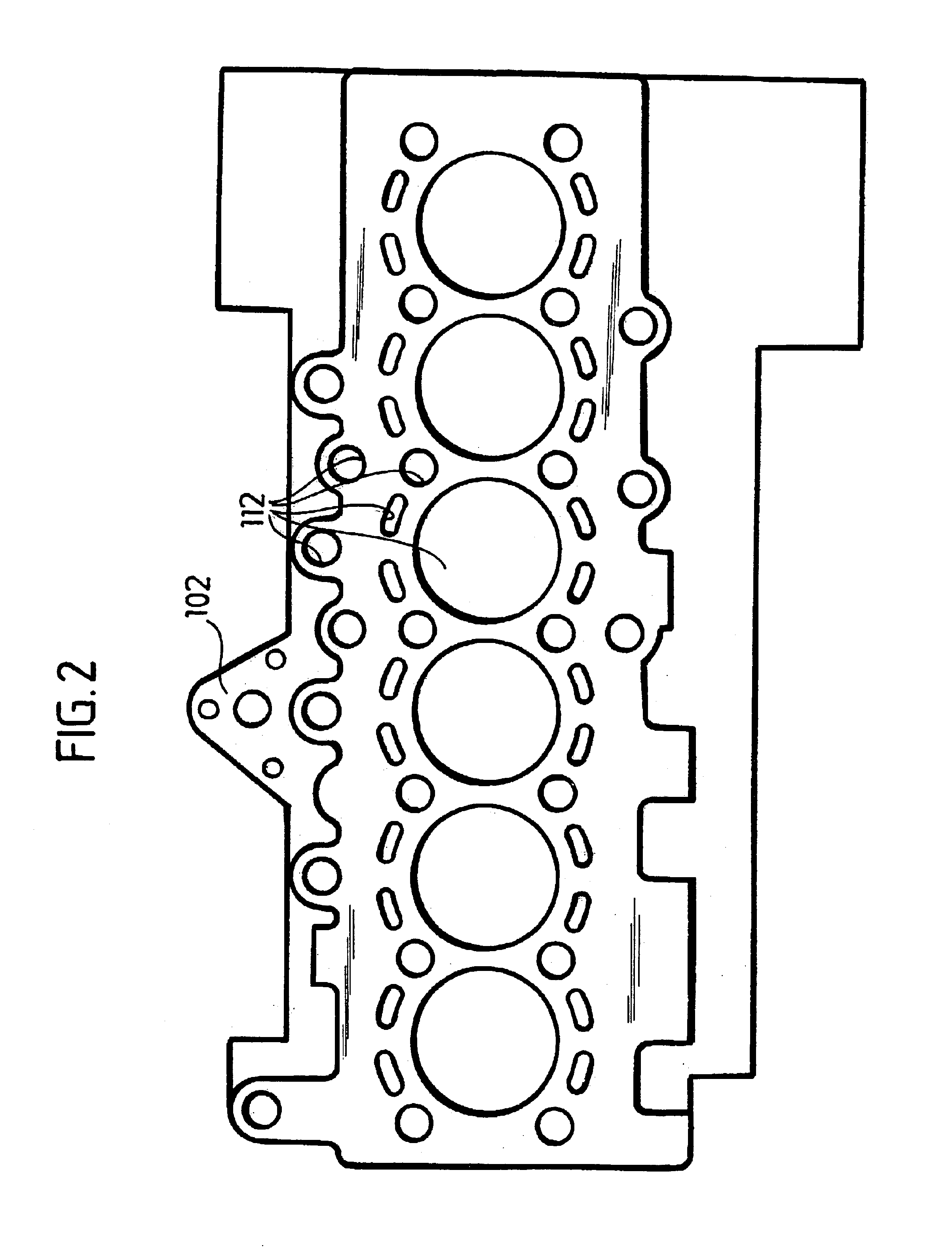
[0058]An apparatus generally designated 100, which is illustrated in FIGS. 1 and 9 to 12, for machining a workpiece 102 shown in FIG. 2, whereby chips are removed from the workpiece, comprises, as is best seen from FIG. 1, a wax filler station 104, a machining station 106, and a wax recovery station 108 and also a conveyor device (not shown) for conveying the workpieces 102 along the conveying direction 110 into the apparatus 100, through the three stations 104, 106 and 108 and out of the apparatus 100.

[0059]The workpieces 102 can be conveyed, for example, by hoisting beams or push rods on a roller conveyor.

[0060]The workpieces 102 which are to be conveyed through the apparatus 100 and machined therein are, for example, engine blocks of an internal combustion engine (see FIG. 2) and have a plurality of recesses 112 extending through the workpiece 102 or ending in the work...


PUM

PropertyMeasurementUnit
Solidification pointaaaaaaaaaa
Flow rateaaaaaaaaaa

Abstract

To provide a method for machining a workpiece, whereby chips are removed from the workpiece, wherein sufficient lubrication of the machining tool and sufficient cooling of the machining tool and the workpiece being machined are ensured, and chips resulting from the machining are simultaneously prevented from remaining inside recesses in the workpiece, a method comprising the following method steps is proposed:
    • introducing a lubricant in a flowable state into at least one recess of the workpiece;
    • solidifying the lubricant in the recess;
    • machining the workpiece, whereby chips are removed from the workpiece, with at least one machining tool coming into direct contact with the lubricant and being lubricated by the lubricant;
    • transforming the lubricant remaining in the recess of the workpiece into the flowable state and removing the lubricant from the workpiece.

Description

[0005]This application is a continuation of international application PCT / EP02 / 006552 filed on Jun. 14, 2002, which is incorporated herein by reference in its entirety and for all purposes.BACKGROUND OF THE INVENTION[0006]The present invention relates to a method for machining a workpiece, whereby chips are removed from the workpiece.[0007]The present invention further relates to an apparatus for machining a workpiece, whereby chips are removed from the workpiece.[0008]During the machining of workpieces, whereby chips are removed from the workpiece, in particular, of workpieces for engine and transmission construction, for example, cylinder heads, crankcases or transmission housings, on transfer lines or in machining centers, very large amounts of liquid coolant are supplied to cool the workpiece and the machining tool, to lubricate the machining tool and to take away the chips removed from the workpiece during the machining.[0009]This conventional lubrication and cooling of the mac...

Claims


Application Information

Patent Timeline
IPC IPC(8): B23Q11/00B23Q11/10
CPCB23Q11/0042B23Q11/10Y10T408/50Y10T29/49995Y10T408/03Y10T408/44B23Q11/1061
Inventor ALVAREZ-VEGA, ANTONIO
Owner DUERR ECOCLEAN GMBH
Why Eureka
Try Eureka