Low voltage or'ing circuits and methods with zero recovery time

a low-voltage or'ing circuit and recovery time technology, applied in the direction of pulse automatic control, pulse technique, electronic switching, etc., can solve the problems of increasing the size of the power supply needed, increasing the cooling needed for the system, and increasing the cost of equipment operation

Inactive Publication Date: 2005-05-10
MAXIM INTEGRATED PROD INC
View PDF3 Cites 32 Cited by
  • Summary
  • Abstract
  • Description
  • Claims
  • Application Information

AI Technical Summary

Problems solved by technology

Thus, failure of the electronic supply or loss of municipal power will result in a takeover by the battery backup system.
At these voltages, a 0.7 volt drop represents a much higher percentage of power dissipation, thereby increasing the size of the power supplies needed, the cooling needed for the system, and making the equipment more expensive to operate.
Also, while the use of Schottky diodes can somewhat reduce the power dissipation in the diodes, the reduction in the power dissipation is only partial.

Method used


Image

  • Low voltage or'ing circuits and methods with zero recovery time
  • Low voltage or'ing circuits and methods with zero recovery time
  • Low voltage or'ing circuits and methods with zero recovery time

Examples


Embodiment Construction

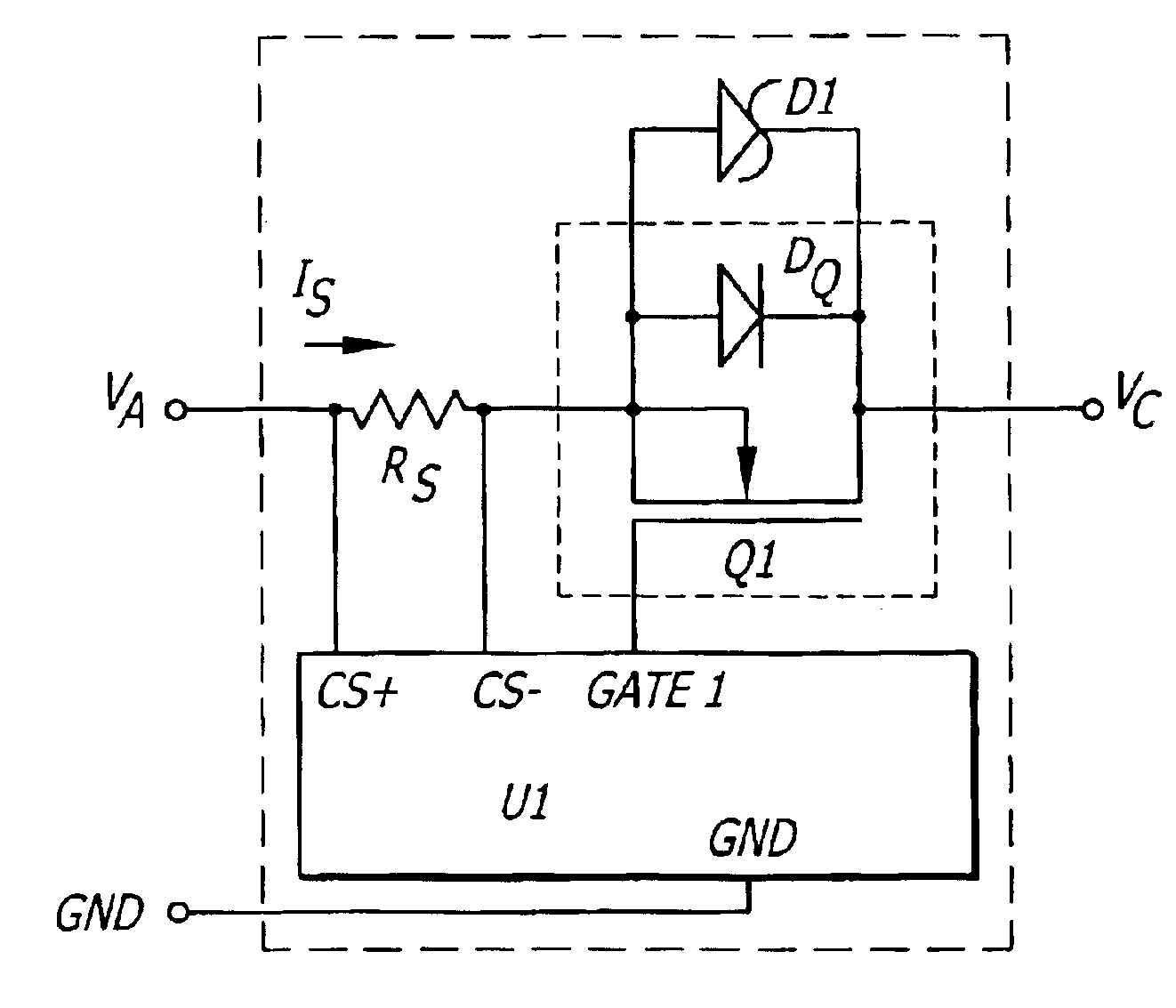
[0032]Now referring to FIG. 7, one embodiment of the present invention may be seen. This embodiment uses an n-channel MOSFET switch Q1 with inherent body diode DQ1. A sense resistor RS is in series with the MOSFET Q1, in the embodiment shown between the input power VA and the drain of the MOSFET, through the sense resistor RS could be located between the source of MOSFET Q1 and the output VC. Coupled to the sense resistor RS is a control circuit U1 for sensing the voltage across the sense resistor RS (pins CS+ and CS−) to control the gate of the MOSFET Q1 by way of an output voltage provided by the controller U1 on the terminal Gate 1. In a typical application, the controller U1 will be provided in integrated circuit form, with the sense resistor RS and the MOSFET Q1 provided in discreet form, as the MOSFET Q1 typically will be a power MOSFET with the sense resistor RS being quite a low valued resistor (0.005 ohms in one embodiment). In alternate embodiments, either the sense resist...


PUM


Abstract

Low voltage drop ORing circuits with zero recovery time and reverse current protection. In use, a MOSFET is coupled between a power supply and a load in a multiple power supply, single load system, or between a power supply and a load in a single power supply, multiple load system, or in both locations in multiple power supply, multiple load systems. A controller senses the current through the MOSFET, and turns the MOSFET off when the current falls below a predetermined threshold current. This allows time for circuit delays and the discharge of the gate of the MOSFET to turn the MOSFET off before the current through the MOSFET car reverse. Turn-on of the MOSFET when the current exceeds the threshold may be purposely slowed to avoid current spikes. Addition of another MOSFET controlled by the controller adds a hot swap capability and the control of the VC slew rate. Various other features and embodiments are disclosed, including various current sensing techniques and circuits using transistors other than MOSFETs.

Description

BACKGROUND OF THE INVENTION[0001]1. Field of the Invention[0002]The present invention relates to the field of power supply circuits.[0003]2. Prior Art[0004]In certain electronic equipment, it is desired or necessary to have two or more power supplies coupled to the equipment so that upon failure of one power supply to provide power to the equipment, another supply will automatically take over. The multiple power supplies may be of the same type or may be of different types. By way of example, redundant electronic supplies may be provided so that a failure of any one supply will not effect the operation of the equipment powered from the redundant supplies. In other cases, one supply might be an electronic supply powered from a municipal power supply, with a second supply being a battery backup supply. Thus, failure of the electronic supply or loss of municipal power will result in a takeover by the battery backup system.[0005]In a redundant supply system, the multiple supplies may be...

Claims


Application Information

Patent Timeline
Patent Type & Authority Patents(United States)
IPC IPC(8): H03K17/16H03K17/30H03K17/693
CPCH03K17/166H03K17/302H03K17/693
Inventor HUYNH, THONG ANTHONY
Owner MAXIM INTEGRATED PROD INC
Why Eureka
Try Eureka