Optical scanning apparatus and an image forming apparatus

a scanning apparatus and image technology, applied in the direction of semiconductor lasers, printers, instruments, etc., can solve the problems of not being able to disclose effective ways, and achieve the effects of preventing temperature increase, preventing the deterioration of laser diodes, and preventing temperature increas

Inactive Publication Date: 2005-05-10
RICOH KK
View PDF22 Cites 19 Cited by
  • Summary
  • Abstract
  • Description
  • Claims
  • Application Information

AI Technical Summary

Benefits of technology

[0017]Accordingly, an object of the present invention is to provide novel optical scanning apparatus and image forming apparatus capable of preventing the temperature increase due to the heat emission from a laser diode, thereby preventing the deterioration of the laser diode.
[0018]According to a further aspect of the present invention, there is also provided a novel method for making an optical scanning apparatus and image forming apparatus capable of preventing the temperature increase due to laser diode heat emission, thereby preventing the deterioration of the laser diode.
[0019]Another object of the invention is to provide such devices with stable optical properties using a simple structure and at low cost.
[0020]These and other objects are achieved according to the present invention by providing novel heat dissipating structures which overcome the limitations of the prior art and provide for improved optical performance and high reliability.

Problems solved by technology

The prior art, such as Japanese Laid-open Patent Publication Nos. 6-246974 and 9-193452, do not disclose effective ways for improving the above-mentioned optical 1 scanning apparatus and image forming apparatus employing such optical scanning apparatus.

Method used


Image

  • Optical scanning apparatus and an image forming apparatus
  • Optical scanning apparatus and an image forming apparatus
  • Optical scanning apparatus and an image forming apparatus

Examples


Embodiment Construction

[0027]In describing the preferred embodiment of the present invention illustrated in the accompanying drawings, specific terminology is employed for the sake of clarity. However, the present invention is not intended to be limited to the specific terminology so selected and it is to be understood that each specific element includes all technical equivalents which operate in a similar manner.

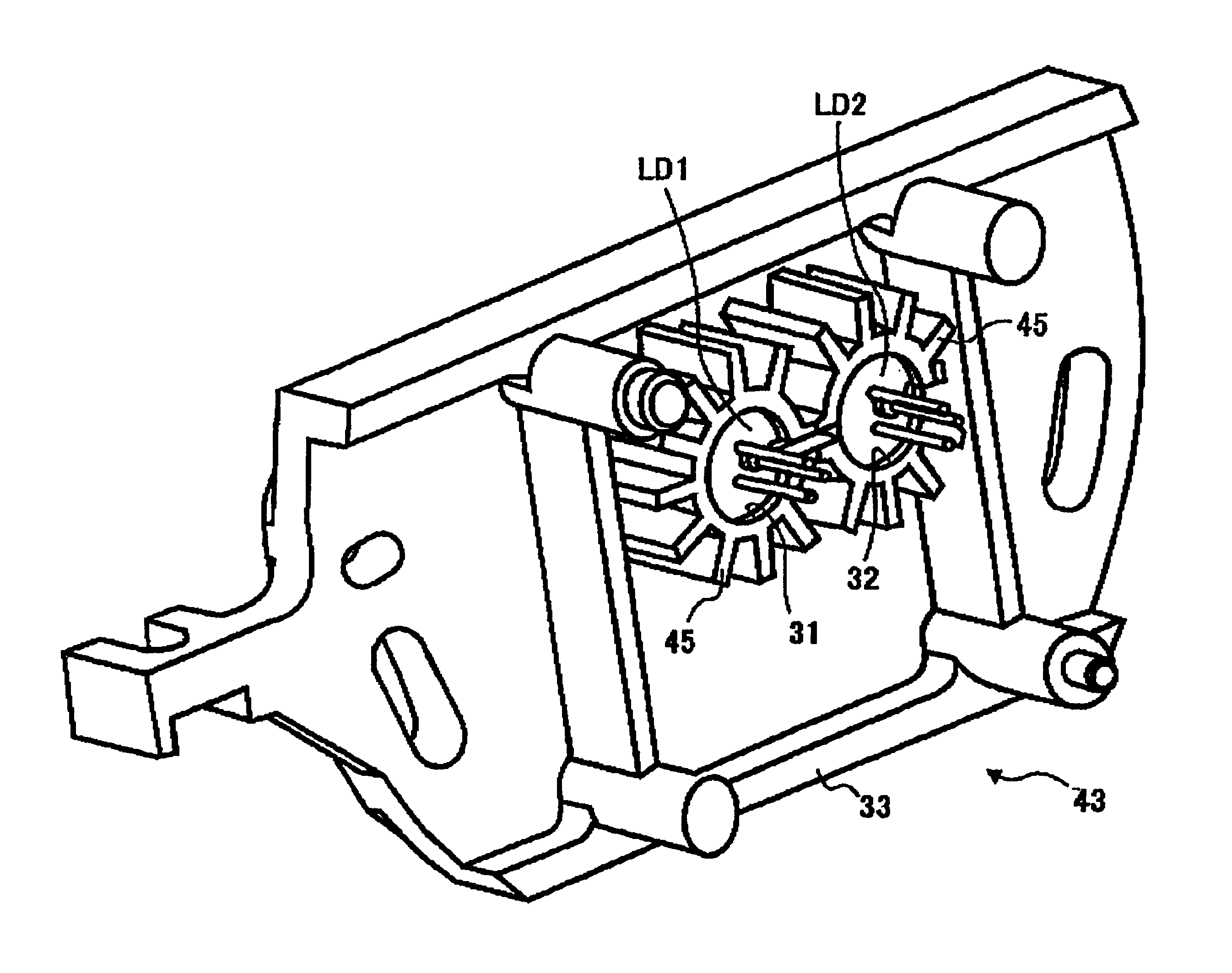
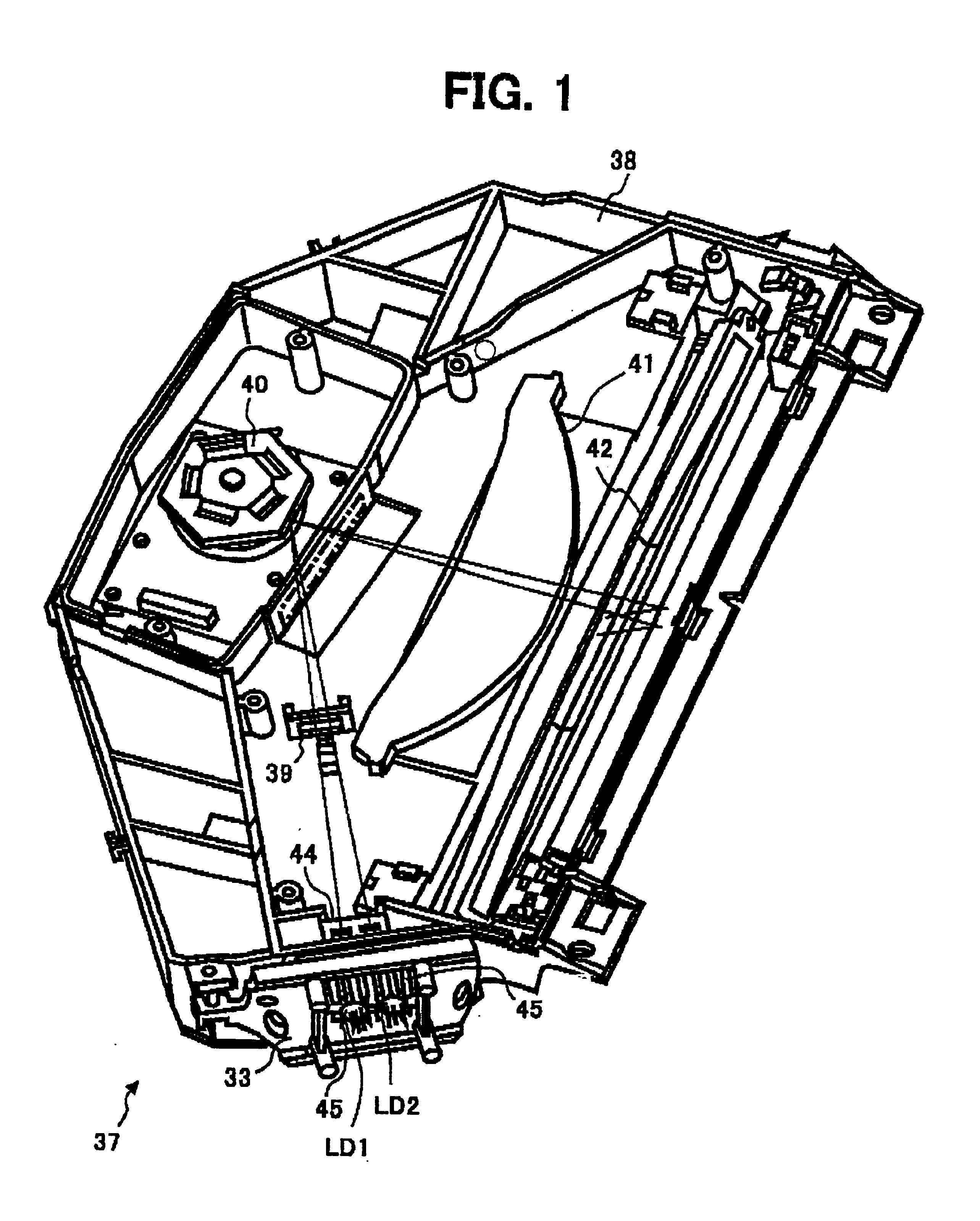
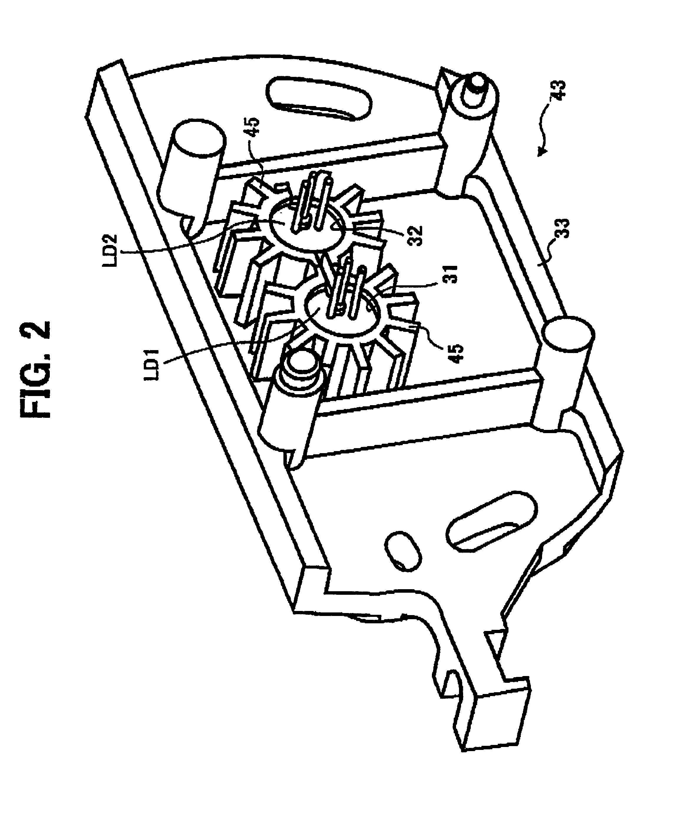
[0028]Referring now to the drawings, wherein like reference numerals designate identical or corresponding parts throughout the several views (graph, diagram), and more particularly to FIGS. 1 through 5, there are illustrated the optical scanning apparatus and the image forming apparatus according to the present invention.

[0029]Other features if the invention will become apparent in the course of the following descriptions of exemplary embodiments which are given for illustration of the invention and are not intended to be limiting thereof.

[0030]In order to attain the aforementioned objects of the...


PUM


Abstract

An optical scanning apparatus including a laser diode light source fittingly inserted into a holding member. The holding member is formed of a resin material having a thermal conductivity of 0.7 w/m°K or more and filled with either glass fiber or metal oxide or both, or aluminum. A heat radiating fin projecting radially is formed on an outer circumferential portion of the cylindrical body of the holding member. With this structure, temperature rise due to heat emission from the laser diode can be suppressed and deterioration of the laser diode can be prevented. This structure simply and inexpensively provides stable optical properties to optical scanning and image forming devices.

Description

CROSS REFERENCE TO RELATED APPLICATIONS[0001]This application claims benefit of priority under 35 U.S.C. §120 to Japanese Patent Application No. JPAP 11-296127 filed in the Japanese Patent Office on Oct. 19, 1999, the entire contents of which are incorporated by reference herein.BACKGROUND OF THF INVENTION[0002]1. Field of the Invention[0003]The present invention relates to an optical scanning apparatus employing a laser diode as a light source and an image forming apparatus employing such an optical scanning apparatus. The image forming apparatus may be used in digital copying machines, printers, facsimile devices, and other devices in which the image is formed by radiating a light laser beam onto a photosensitive body.[0004]2. Discussion of the Background[0005]Many image forming devices are provided for use in copying machines, printers, facsimiles, etc., in which a light beam output from a laser diode is radiated onto a photosensitive body, thereby forming an electrostatic latent...

Claims


Application Information

Patent Timeline
Patent Type & Authority Patents(United States)
IPC IPC(8): B41J2/435B41J2/44G02B26/10G03B27/52G03G15/043H01S5/024H01S5/00B41J2/47G03G15/04
CPCB41J2/471
Inventor BANNAI, KAZUNORI
Owner RICOH KK
Why Eureka
Try Eureka