Head gimbal assembly

a head gimbal and assembly technology, applied in the direction of integrated arm assemblies, maintaining head carrier alignment, instruments, etc., can solve the problems of limited transmission frequency and increase the frequency of recording and reproducing, and achieve the effect of more enhanced recording frequency and reproducing frequency

Inactive Publication Date: 2005-05-10
TDK CORPARATION +1
View PDF13 Cites 70 Cited by
  • Summary
  • Abstract
  • Description
  • Claims
  • Application Information

AI Technical Summary

Benefits of technology

[0007]It is therefore an object of the present invention to provide an HGA, w

Problems solved by technology

However, this increasing in the transmission frequency is limited and thus it i

Method used


Image

  • Head gimbal assembly
  • Head gimbal assembly
  • Head gimbal assembly

Examples


Embodiment Construction

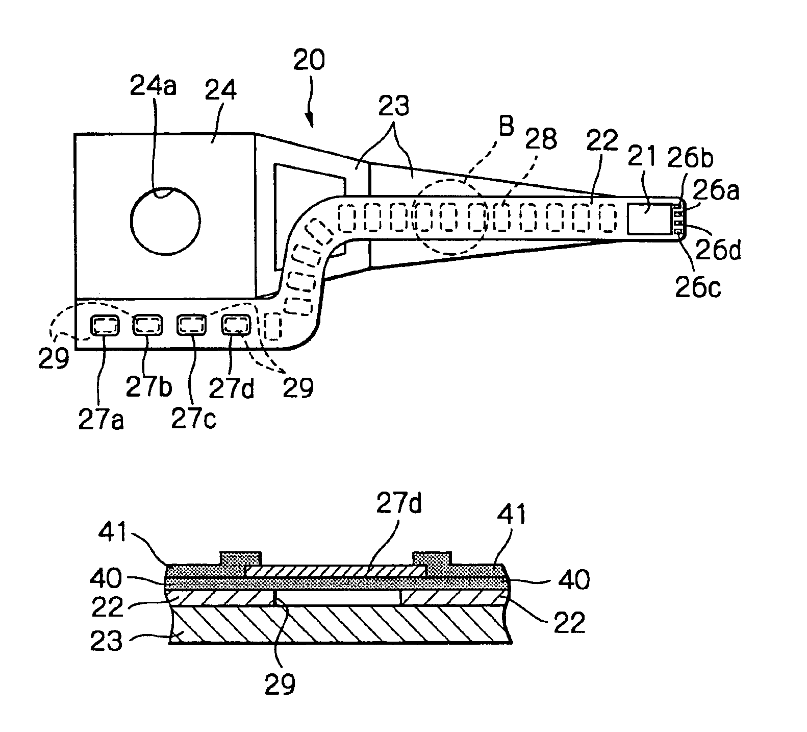
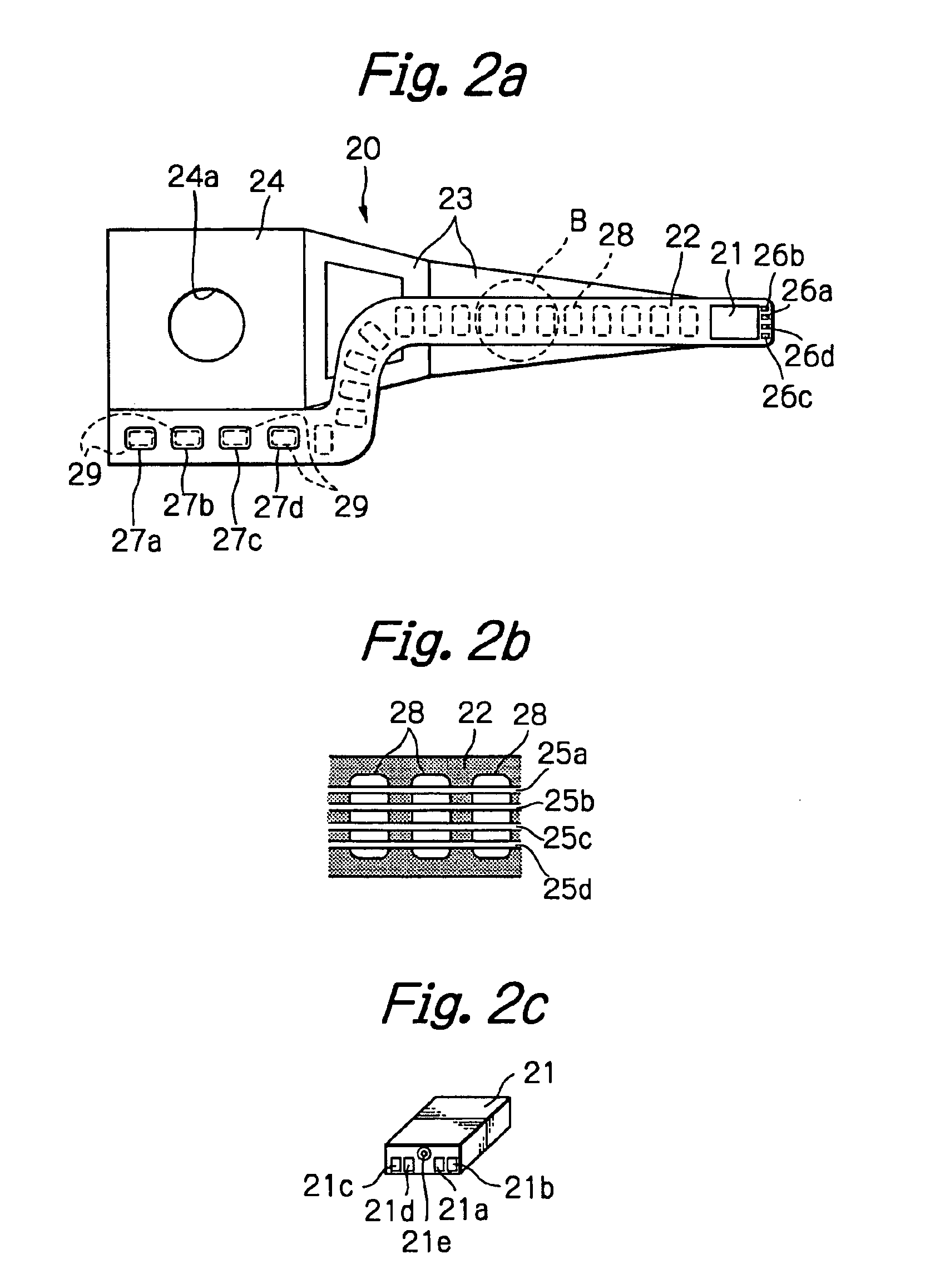
[0050]FIG. 2a illustrates a preferred embodiment of a HGA according to the present invention, FIG. 2b illustrates a structure of signal trace conductors and a flexure in a circle B shown in FIG. 2a, FIG. 2c illustrates a structure of a magnetic head slider shown in FIG. 2a, FIG. 3 illustrates in detail a section of external signal connection pads shown in FIGS. 2a and 2b, and FIG. 4 is a IV—IV line sectional view of FIG. 3. In FIG. 2a, indication of the signal trace conductors is omitted.

[0051]As shown in these figures, the HGA is assembled by fixing a magnetic head slider 21 having at least one thin-film magnetic head element 21e to a top end section of a suspension 20. Although it is not shown, a drive IC chip for driving the head element 21e and for driving the head element and for amplifying a read-out signal from the head element may be mounted on a middle section of this suspension 20.

[0052]The suspension 20 is substantially constituted by a resilient flexure 22 which carries ...


PUM


Abstract

An HGA includes a magnetic head slider with at least one thin-film magnetic head element, a metal suspension for supporting the magnetic head slider, signal trace conductors formed via an insulation material layer on the metal suspension, for transmitting signals of the at least one thin-film magnetic head element, and external signal connection pads formed via an insulation material layer on the metal suspension and electrically connected to the signal trace conductors. At least part of the metal suspension under the external signal connection pads is removed.

Description

FIELD OF THE INVENTION[0001]The present invention relates to a head gimbal assembly (HGA) used in a magnetic disk storage apparatus or in a magneto-optical disk storage apparatus.DESCRIPTION OF THE RELATED ART[0002]An HGA with a metal suspension on which a lead conductor pattern of trace conductors and connection pads for a thin-film magnetic head element is formed is known from, for example, Ohe et al. (Japanese Patent Publication 06215513 A) and Erpelding et al. (U.S. Pat. No. 4,996,623).[0003]Ohe et al. discloses forming of a lead conductor pattern for connections with a thin-film magnetic head element on a load beam by using photolithography, whereas Erpelding et al. discloses a laminated suspension provided with a flexible plastic material sheet, a stainless steel layer bonded to one surface of the sheet and a copper layer having a pattern of trace conductors for electrical connections and bonded to the other surface of the sheet.[0004]In both of these known arts, the trace con...

Claims


Application Information

Patent Timeline
IPC IPC(8): G11B5/48G11B5/60G11B21/21
CPCG11B5/486G11B5/484
Inventor SHIRAISHI, MASASHIWADA, TAKESHIHONDA, TAKASHI
Owner TDK CORPARATION
Why Eureka
Try Eureka