A method and system for parallel transmission of multi-channel carrier optical signals

A technology for transmitting systems and optical signals, applied in multi-carrier systems, electromagnetic transmitters, etc., can solve the problems of low switching speed, single transmission frequency, delay, etc., and achieve low frequency phase noise, high frequency resolution, and small phase drift Effect

Active Publication Date: 2016-06-01
INST OF AUTOMATION CHINESE ACAD OF SCI
View PDF2 Cites 0 Cited by
  • Summary
  • Abstract
  • Description
  • Claims
  • Application Information

AI Technical Summary

Problems solved by technology

[0004] (1) Single transmission frequency: The existing carrier optical system generally designs the transmission frequency for fixed applications, and the carrier optical signal frequency depends on the signal generator, which is only suitable for systems designed for fixed applications and is inconvenient to load in other working environments
[0005] (2) Single optical path: The number of optical paths required by different carrier optical applications is limited to its own needs, and it is difficult for the existing system to cope with the need to expand the optical path
[0006] (3) Frequency switching problem: Generally, the carrier optical transmission system has a fixed frequency and is inconvenient to adjust. A few frequency adjustable systems have phase discontinuity, slow switching speed, and certain delays when switching frequency, and are not suitable for fast switching frequency. , and requires phase continuity when switching
[0007] (4) Carrier light transmission power is unstable: The stability of the transmission power of carrier light as a light source signal is extremely important. Existing systems generally rely on circuits such as constant current drive to control output power. There is a certain current drift in the LED driver module. In addition, the light emitting device The performance itself cannot guarantee that there will be no instantaneous jump when the driving current is stable, and the overall performance needs to be improved.
[0008] (5) Poor portability: The existing carrier optical system has a low degree of integration, and does not consider integrating all modules. It has a large volume and low portability
[0009] (6) Low degree of intelligence: the carrier optical system cannot be intelligent when it is working, the adjustment process is more complicated, it relies on manual adjustment, and it is not convenient to use
[0010] (7) High power consumption: The signal generator itself needs 220V voltage, and the power consumption is relatively large, and the light-emitting devices mostly use lasers and LDs, and the power consumption is higher than that of LEDs, which is not environmentally friendly and energy-saving.
[0011] In short, the existing carrier optical transmission system has a single design working mode, low switching speed, discontinuous phase, less optional transmission frequency, poor optical path expansion, low overall portability, high power consumption, and is not environmentally friendly. Although it can cope with certain applications , but the adaptability is not high, and the degree of intelligence is low

Method used


Image

  • A method and system for parallel transmission of multi-channel carrier optical signals
  • A method and system for parallel transmission of multi-channel carrier optical signals
  • A method and system for parallel transmission of multi-channel carrier optical signals

Examples


Embodiment Construction

[0042] In order to make the objectives, technical solutions and advantages of the present invention clearer, the present invention will be further described in detail below in conjunction with specific embodiments and with reference to the accompanying drawings.

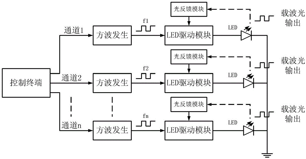
[0043] Such as figure 1 As shown, the system is divided into the following modules: square wave generation module, LED drive module, optical feedback module, and control terminal module. The details are as follows:

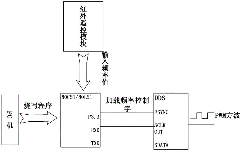
[0044] 1. Carrier light undertakes the task of loading other useful optical signals, and its performance requirements are very high in applications. Therefore, the frequency and duty cycle of the carrier light square wave must be stable and accurate. This requirement is not only reflected in the transmitting end, but for any receiving end, stable frequency and duty cycle are necessary for the conversion and demodulation of later signals. . The square wave generating module of the present invention uses DDS t...


PUM


Abstract

The invention discloses a method and a system of parallel emission of multichannel carrier light signals. The system drives a direct numerical frequency synthesizer chip to generate a square signal through intellectualized control of a control terminal, wherein frequency and phase positions of the square signal are continuous and controllable, and the system outputs the square signal to control a light emitting diode (LED) to flicker in fixed frequency. During the working process of the LED, an LED drive module and an optical feedback module act together and enable the LED to output carrier light signals which are stable in power in long power mode, the optical feedback module feeds received LED power instability fluctuation back by using a photovoltaic conversion diode and restrains power fluctuation by being combined with the LED drive module, and furthermore the multichannel carrier light signals which are controllable in frequency and phase position are generated by arranging a multichannel square signal generator and an LED module in parallel. The whole system is intelligent and controllable, high in integration level, low in power consumption, stable and reliable in work, and wide in application scope, can be extended in multiple channels, and is an integrated carrier light generating system.

Description

Technical field [0001] The present invention relates to a method and system for transmitting optical signals, and in particular to a method and system for parallel transmitting multi-channel carrier optical signals. Background technique [0002] With the development of optoelectronic technology, there are more and more occasions for optical signals to be used as carrier signals. For example, in parallel spectrum detection technology, multiple carrier lights need to be emitted at the same time, enter the substance to be detected, and send relevant information about the substance to be detected to the receiving end. This kind of multi-channel optical signal transceiving scheme has higher requirements on the frequency, phase and stability of the multi-channel optical signal. For another example, optical communication is the main method of future communication. Use light waves as the information carrier to send useful signals. Carrier light plays a vital role as the carrier in optica...

Claims


Application Information

Patent Timeline
Patent Type & Authority Patents(China)
IPC IPC(8): H04L27/36H04B10/50
Inventor 张鑫左年明蒋田仔蔡正辰
Owner INST OF AUTOMATION CHINESE ACAD OF SCI
Why Eureka
Try Eureka