Computer-assisted bone densitometer

a computer-aided bone densitometer and densitometer technology, which is applied in the field of xray bone densitometers, can solve the problems of additional expense and inconvenience, and the inability to recognize improper scans, so as to reduce errors and reduce acquisition errors.

Inactive Publication Date: 2005-05-10
GE MEDICAL SYST GLOBAL TECH CO LLC
View PDF14 Cites 19 Cited by
  • Summary
  • Abstract
  • Description
  • Claims
  • Application Information

AI Technical Summary

Benefits of technology

[0005]The present invention provides computer-assisted densitometry in which software monitors the steps of acquiring and analyzing the data with the intent of identifying potential positioning and / or analysis errors. This computer assistance provides a backup to the operator or physician review of the measurement, advising them of a possible problem. Computer assistance together with the oversight of the physician or operator may significantly decrease errors in the acquisition and analysis of the data, and decrease errors from any other source that affects the ultimate clinical measurement.

Problems solved by technology

if a problem with the scan is not detected promptly, the patient may need to be recalled and scanned again, incurring additional expense and inconvenience.
It is also possible that improper scanning may not be recognized at all, producing an erroneous result.

Method used


Image

  • Computer-assisted bone densitometer
  • Computer-assisted bone densitometer
  • Computer-assisted bone densitometer

Examples


Embodiment Construction

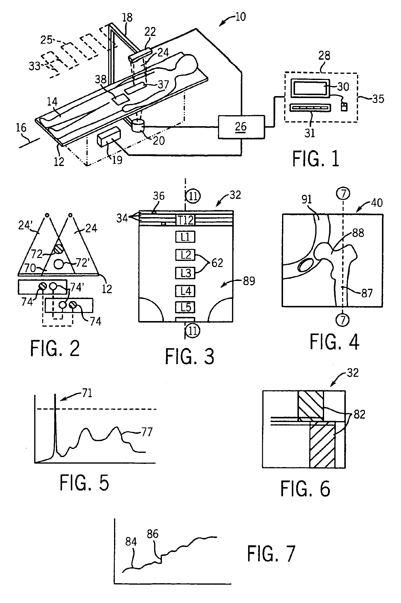
[0020]Referring now to FIG. 1, a bone densitometer, 10, includes a patient table, 12, providing a horizontal surface for supporting a patient in supine or lateral position along a longitudinal axis 16.

[0021]A C-arm 18, has a lower end positioned beneath the patient table 12 to support an x-ray source 20 and an upper end positioned above the patient table 12 supporting an x-ray detector 22. The x-ray source 20 and x-ray detector 22 may be moved in a raster pattern 25 so as to trace a series of transverse scans 33 of the patient during which dual energy x-ray data are collected by the x-ray detector 22. This raster motion is produced by actuators under control of a translation controller 19 according to methods well understood in the art.

[0022]In the preferred embodiment, the x-ray source 20 provides two x-ray energies and the x-ray detector 22 is a multi-element CZT detector providing for energy discrimination. However, other methods of dual energy measurement including those providi...


PUM

PropertyMeasurementUnit
densityaaaaaaaaaa
areaaaaaaaaaaa
bone mineral densityaaaaaaaaaa

Abstract

An x-ray densitometry system provides computer assistance to the operator in identifying possible sources of scanning or analysis error through computer review of the acquired data, operator input, and the ultimate diagnostic outputs.

Description

BACKGROUND OF INVENTION[0001]The present invention relates generally to x-ray bone densitometers for measuring bone health and particularly to a bone densitometer providing computer assisted detection of measurement artifacts and operator errors.[0002]X-ray bone densitometers make measurements at two x-ray energies to provide separate attenuation images of two basis materials, typically bone and soft tissue. The bone attenuation image is substantially free from attenuation caused by soft tissue allowing areal bone density (g / cm2) to be accurately determined in vivo for assessments of bone strength and health. The bone attenuation image also provides improved definition of bone outlines, allowing measurements, for example, of bone morphology (e.g., vertebral height) such as may be useful for detecting crush fractures associated with osteoporosis.[0003]In order to achieve accurate quantitative results from a bone densitometer, the patient must be properly positioned, motionless during...

Claims


Application Information

Patent Timeline
Patent Type & Authority Patents(United States)
IPC IPC(8): A61B6/00G06T1/00
CPCA61B6/505A61B6/482A61B6/4035A61B6/4241
Inventor FAULKNER, KENNETH G.BARDEN, HOWARD S.
Owner GE MEDICAL SYST GLOBAL TECH CO LLC
Why Eureka
Try Eureka