Single-balanced shield electrode configuration for use in capacitive displacement sensing systems and methods

a capacitive displacement and shield electrode technology, applied in the direction of force measurement, instruments, force measurement, etc., can solve the problems of insufficient, inconvenient, insufficient, etc., to achieve the effect of convenient, economical, reliable and compa

Inactive Publication Date: 2005-05-17
ANDERMOTION TECH
View PDF11 Cites 23 Cited by
  • Summary
  • Abstract
  • Description
  • Claims
  • Application Information

AI Technical Summary

Benefits of technology

[0005]It should be appreciated that the electrical connections and or capacitive coupling provided by the embodiments indicated above may be inconvenient, unreliable, or “insufficient” to effectively and fully ground the shield electrode in a variety of desirable capacitance-type measuring device configurations and applications. Furthermore, the amplifier circuitry indicated above that feeds back a capacitively coupled signal of the opposite polarity to the shield electrode in order to actively control its voltage or potential introduces additional complexity and cost and may also be inconvenient, unreliable, or “insufficient” to effectively and fully control the voltage or potential of the shield electrode in a variety of desirable capacitance-type measuring device configurations and applications. Thus, a capacitance-type measuring device that can overcome the foregoing problems and disadvantages, individually or in combination, is desirable.
[0007]Alternatively, rather than replacing or eliminating the previously outlined electrical ground connection or active sensing and control of a shield electrode(s) voltage, the present invention can be used to maintain the shield electrode(s) at an approximately constant voltage or potential during capacitive displacement or position measurements in combination with such electrical ground connection or active sensing and control configurations and methods, in order to provide an additional measure of signal stability and reliability, and / or to relatively reduce the complexity and / or operational requirements of the electrical ground connection or active sensing and control elements. In either case, the present invention provides a number of desirable features, including relatively reduced cost, increased reliability, and high accuracy displacement sensing.
[0008]A capacitive encoder including a signal-balanced shield electrode configuration is disclosed. In accordance with one aspect of the invention, the signal-balanced shield electrode is patterned in a manner that complements the layout of the transmitter electrodes of the capacitive encoder, such that the signal-balanced shield electrode inherently or passively floats at a nominally constant electrical potential or voltage when coupled to the signals present on the transmitter electrodes. The resulting capacitive encoder is thus more economical to build, convenient to install, and reliable during operation than capacitive encoders which use an electrical connection, compensation drive circuitry, or grounding in order to control the voltage or potential of a shield member that operates at a voltage or potential that is not inherently constant.
[0025]Hence, the invention overcomes the disadvantages of prior art capacitive displacement sensing devices that use electrically connected, externally coupled, or actively controlled shield electrodes, in order to provide either rotary or linear measurements with sensing systems that are more convenient, economical, reliable and compact

Problems solved by technology

It should be appreciated that the electrical connections and or capacitive coupling provided by the embodiments indicated above may be inconvenient, unreliable, or “insufficient” to effectively and fully ground the shield electrode in a variety of desirable capacitance-type measuring device configurations and applications.
Furthermore, the amplifier circuitry indicated above that feeds back a capacitively coupled signal of the opposite polarity to the shield electrode in order to actively control its voltage or potential introduces additional complexity and cost and may also be inconvenient, unreliable, or “insufficient” to effectively and fully control the voltage or potential of the shield electrode in a variety of desirable capacitance-type measuring device configurations and applications.

Method used


Image

  • Single-balanced shield electrode configuration for use in capacitive displacement sensing systems and methods
  • Single-balanced shield electrode configuration for use in capacitive displacement sensing systems and methods
  • Single-balanced shield electrode configuration for use in capacitive displacement sensing systems and methods

Examples


Embodiment Construction

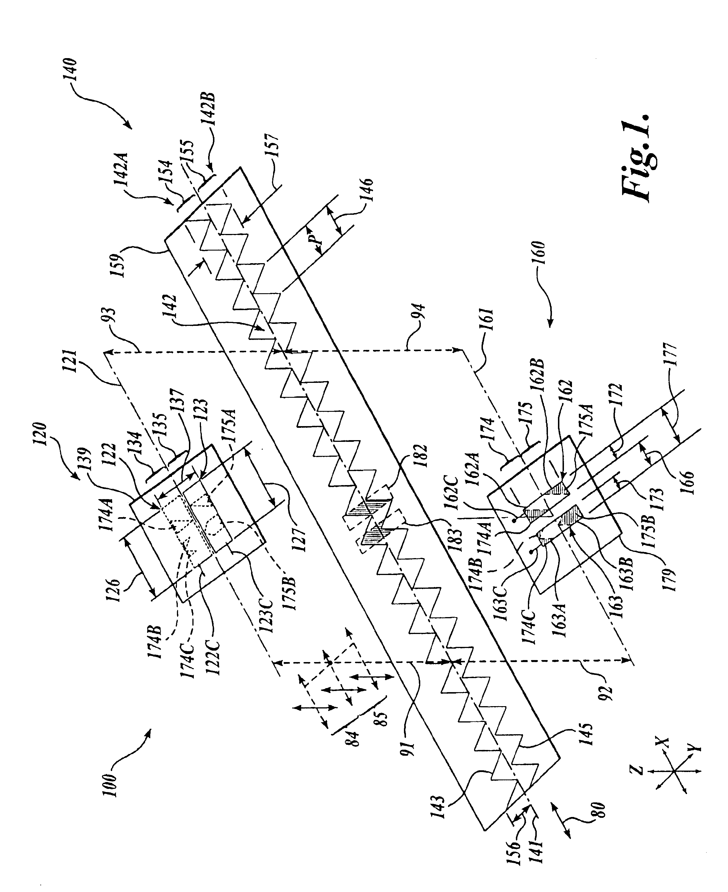
[0047]FIG. 1 shows a generic first exemplary embodiment of a signal-balanced electrode configuration 100 according to this invention that is usable in a capacitive encoder according to this invention. As shown in FIG. 1, the first exemplary embodiment of a signal-balanced electrode configuration 100 includes a transmitter electrode configuration 120 carried on a transmitter electrode member 139, a shield electrode configuration 140 carried on a shield electrode member 159, and a receiver electrode configuration 160 carried on a receiver electrode member 179. The shield electrode member 159 acts as the scale for displacement measurement, and various shield electrode configurations, shield electrode members and / or shield electrodes may also be referred to as scales herein. In various embodiments, the shield electrode configuration 140 should be understood to comprise a segment of an arbitrarily longer shield electrode configuration 140.

[0048]Also shown in FIG. 1 are a measuring axis / d...


PUM

PropertyMeasurementUnit
DC voltageaaaaaaaaaa
voltageaaaaaaaaaa
voltage changeaaaaaaaaaa

Abstract

A capacitive encoder includes a signal-balanced shield electrode configuration that does not require electrical ground connection or active sensing and control in order to maintain the shield electrode(s) at a sufficiently constant voltage during capacitive position measurements. The shield electrode configuration is positioned in a capacitive coupling gap between transmitter electrodes and receiver electrodes during operation. The shield electrode configuration is patterned in a manner that complements the layout of the transmitter electrodes, such that the shield electrode configuration inherently floats at a nominally constant electrical potential when coupled to the signals present on the transmitter electrodes. The resulting capacitive encoder is thus more economical to build, convenient to install, and reliable during operation than capacitive encoders which use an electrical connection, compensation drive circuitry, or grounding in order to control the potential of a shield member that operates at a potential that is not inherently constant.

Description

FIELD OF THE INVENTION[0001]This invention relates generally to displacement sensing capacitive encoders, and more particularly to capacitive encoders including a scale having signal-balanced shield electrode configuration that does not require an electrical connection or grounding of the shield electrode, in order to provide low cost, reliable, and high accuracy displacement sensing.BACKGROUND OF THE INVENTION[0002]Numerous capacitance-type measuring devices for making linear and angular displacement or position measurements have been developed wherein two members that are fixed relative to each other include respective capacitive electrodes that are capacitively coupled between the two support members and a third member is relatively movable between the two members to alter their capacitive coupling. The third member alters their capacitive coupling in a manner corresponding to the position of the third member relative to the first two members. The capacitive coupling affects one ...

Claims


Application Information

Patent Timeline
Patent Type & Authority Patents(United States)
IPC IPC(8): G01D5/241G01L1/12G01L1/20G01L3/02
CPCG01D5/2415
Inventor ANDERMO, NILS INGVAR
Owner ANDERMOTION TECH
Why Eureka
Try Eureka