Fuel injection valve

a fuel injection valve and valve body technology, applied in the direction of electric control, magnetic bodies, machines/engines, etc., can solve the problems of shortening the closing time to a mere negligible extent, costly construction of appropriate control elements, and the known fuel injector, etc., to achieve rapid opening operation, low activation output, and accelerate the effect of closing operation

Inactive Publication Date: 2005-05-17
ROBERT BOSCH GMBH
View PDF13 Cites 32 Cited by
  • Summary
  • Abstract
  • Description
  • Claims
  • Application Information

AI Technical Summary

Benefits of technology

[0006]The fuel injector of the present invention has the advantage over the related art that, due to the combination of a double-coil concept and the principle of the armature-free path which, by one prestroke and one positioning spring for each magnetic coil, allows a rapid opening operation and an active and, thus, accelerated closing operation, so that a fuel injector is able to be realized which has low activation outputs of the magnetic circuits and high switching dynamics.
[0007]It is also advantageous that the spring constants of the positioning springs are low compared to the spring constants of the restoring spring, thereby obviating a strengthening of the restoring spring.
[0008]By using two flanges which are in force-locked connection with the valve needle, in combination with the weak positioning springs, an armature free-path system is able to be realized that is mechanically simple and cost-effective.
[0009]The free paths of the armature advantageously amount to approximately half the total lift of the armatures of the magnetic circuit, so that the armatures are kept in oscillating center positions by an appropriately adjusted timing, which results in high switching dynamics.

Problems solved by technology

However, the construction of appropriate control elements is costly and shortens the closing times to a merely negligible extent.
A disadvantage of the fuel injector known from German Patent No.
DE 23 06 007, in particular, is the costly manufacture of a system having three switching circuits controlling three windings of the magnetic coil.
The increased space required by the switching circuits is an additional disadvantage.

Method used


Image

  • Fuel injection valve
  • Fuel injection valve
  • Fuel injection valve

Examples


Embodiment Construction

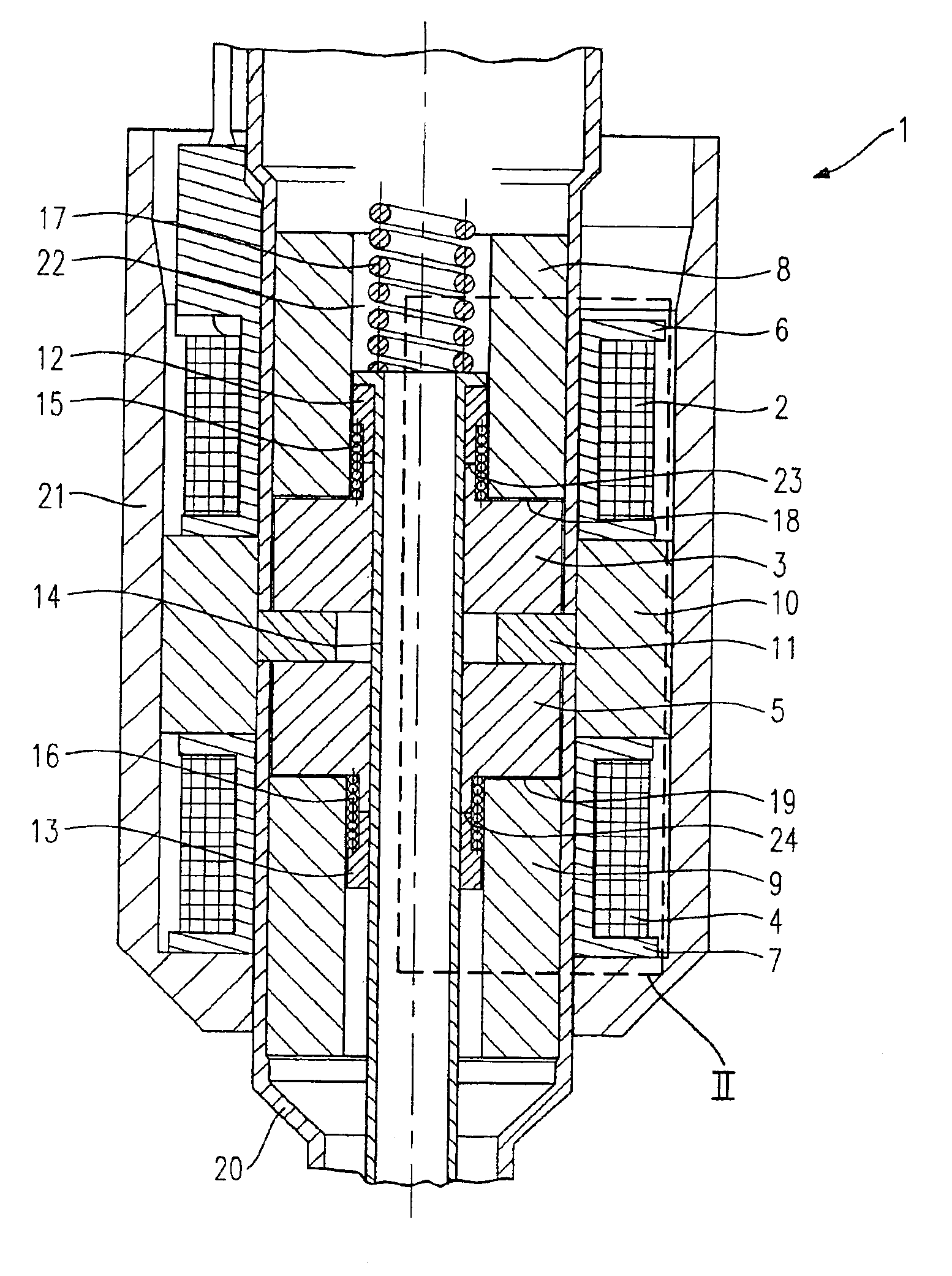
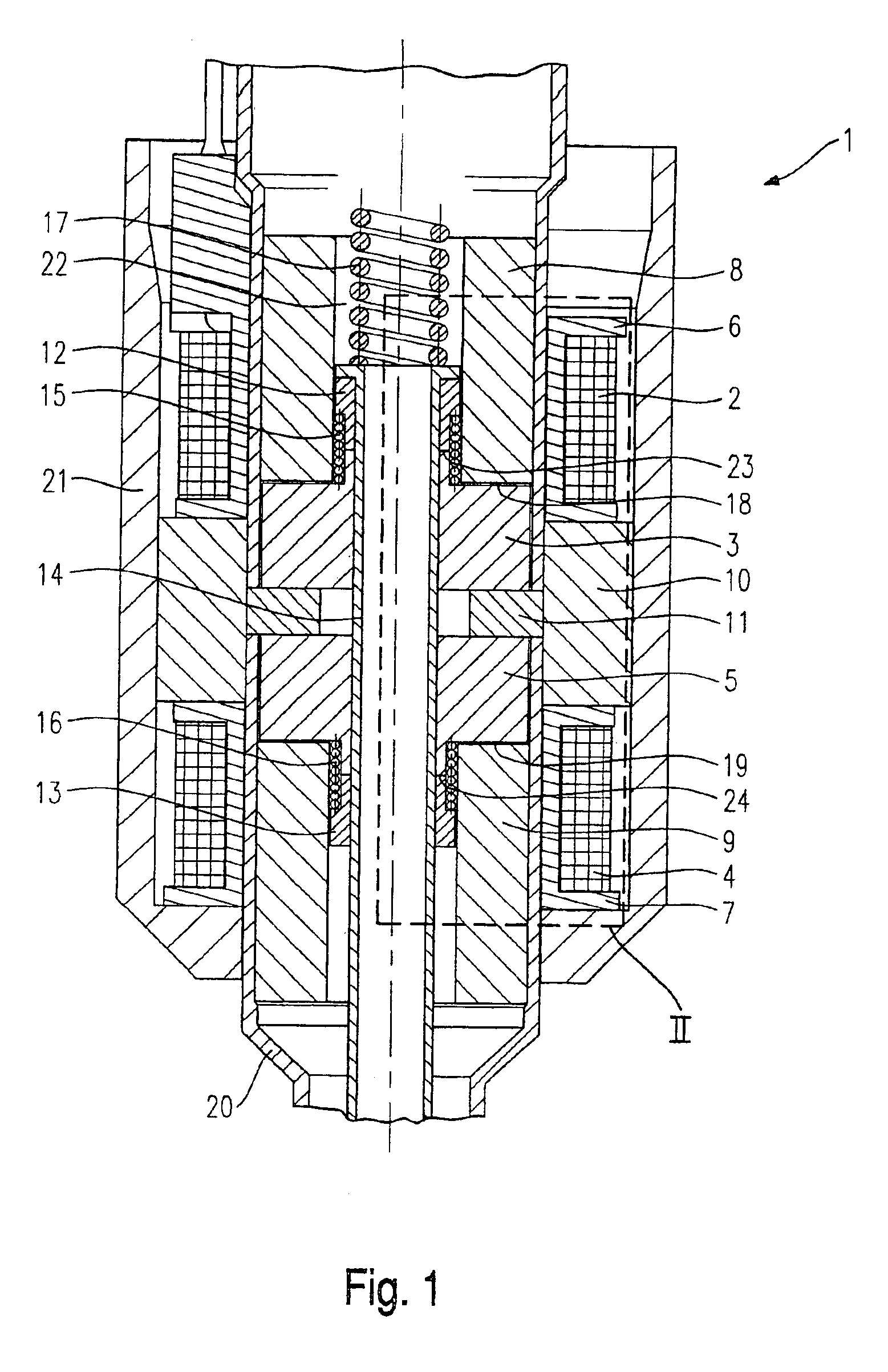
[0014]FIG. 1 shows a part-sectional view of the center section of a fuel injector 1. Fuel injector 1 is used especially for the direct injection of fuel into the combustion chamber (not shown) of a mixture-compressing internal combustion engine having externally supplied ignition. Fuel injector 1 may be implemented as an inwardly opening or an outwardly opening fuel injector 1. Fuel injector 1 shown in FIG. 1 is a fuel injector that opens to the inside.

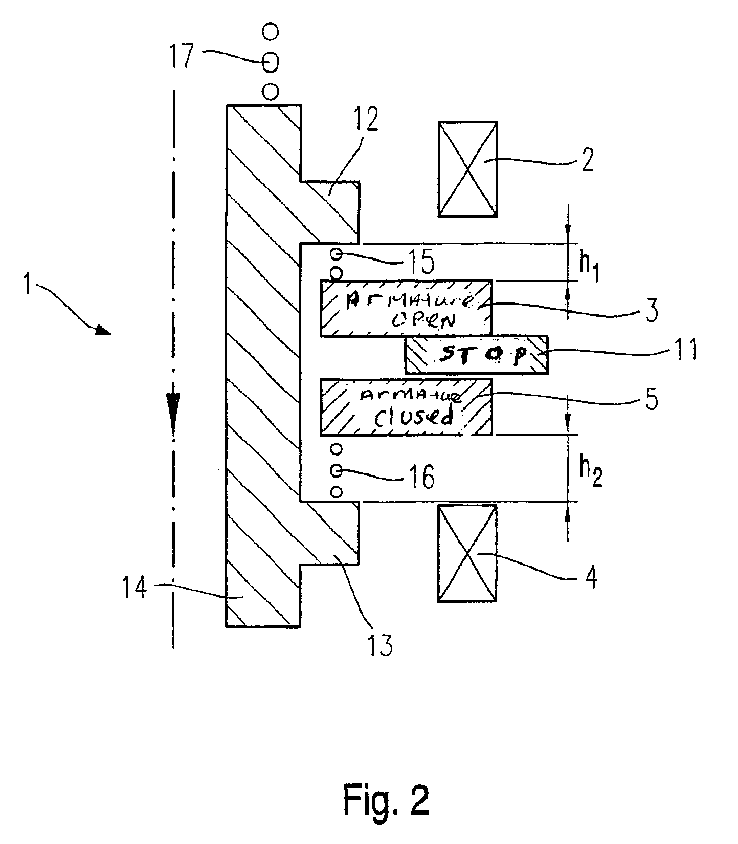
[0015]Fuel injector 1 includes a first magnetic coil 2 cooperating with a first armature 3, and a second magnetic coil 4 cooperating with a second armature 5. First magnetic coil 2 is wound on a first coil brace 6, and second magnetic coil 4 is wound on a second coil brace 7. First magnetic coil 2 is surrounded by a first core part 8, while second magnetic coil 4 is surrounded by a second core part 9. First magnetic coil 2 and second magnetic coil 4 are separated from one another in the axial direction by a segment 10. First armature ...


PUM


Abstract

A fuel injector, in particular a fuel injector for fuel-injection systems of internal combustion engines, includes a first magnetic coil cooperating with a first armature, a second magnetic coil cooperating with a second armature, and a valve needle which is in force-locking connection with the first armature via a first flange and to the second armature via a second flange, to actuate a valve-closure member. A restoring spring acts upon the valve needle in a closing direction of the fuel injector. A first positioning spring, situated between the first flange and the first armature, acts upon the first armature in the closing direction of the fuel injector, while a second positioning spring, situated between the second flange and the second armature, acts upon the second armature in an opening direction of the fuel injector.

Description

BACKGROUND INFORMATION[0001]The closing times of fuel injectors are lengthened not only by adhesion forces between the armature and core but also by eddy currents. To reduce the delays, it is known, for example, to select a heavier design for the restoring spring acting upon the armature. To ensure that the opening times of the fuel injector will not be adversely affected by the increased restoring force of the restoring spring, stronger magnetic circuits must be developed which require larger dimensions of the magnetic coils, higher supply voltages, a greater number of turns per unit of length and more expensive magnet materials for their operation.[0002]In addition, to speed up the decay of the residual field, it is known to allow a current to flow through the magnetic coil in the reverse direction once the current pulse energizing the fuel injector has come to an end. However, the construction of appropriate control elements is costly and shortens the closing times to a merely ne...

Claims


Application Information

Patent Timeline
Patent Type & Authority Patents(United States)
IPC IPC(8): F02M51/06F02D41/20F02M51/00
CPCF02M51/0685F02M51/0617F02D41/20F02D2041/2079
Inventor RIEGER, FRANZYILDIRIM, FEVZIEICHENDORF, ANDREASHOHL, GUNTHERHUBEL, MICHAELSTEIN, JURGEN
Owner ROBERT BOSCH GMBH
Why Eureka
Try Eureka