
VTOL personal aircraft

Inactive Publication Date: 2005-05-17
MILDE JR KARL F
View PDF20 Cites 66 Cited by
  • Summary
  • Abstract
  • Description
  • Claims
  • Application Information

AI Technical Summary

Benefits of technology

[0011]It is a principal object of the present invention to provide an advantageous design for a Personal Aircraft which enables the aircraft to take off, fly, and land in extremely confined areas, but which is extremely fuel efficient in transporting a payload from point to point.
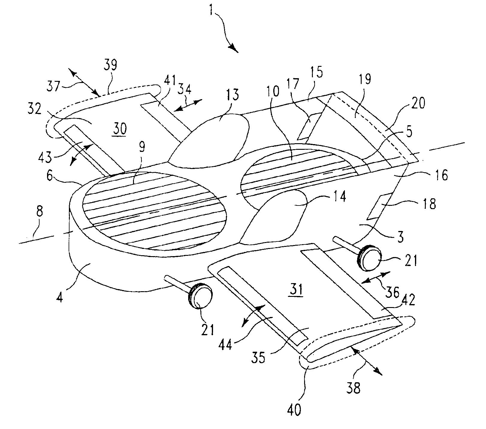
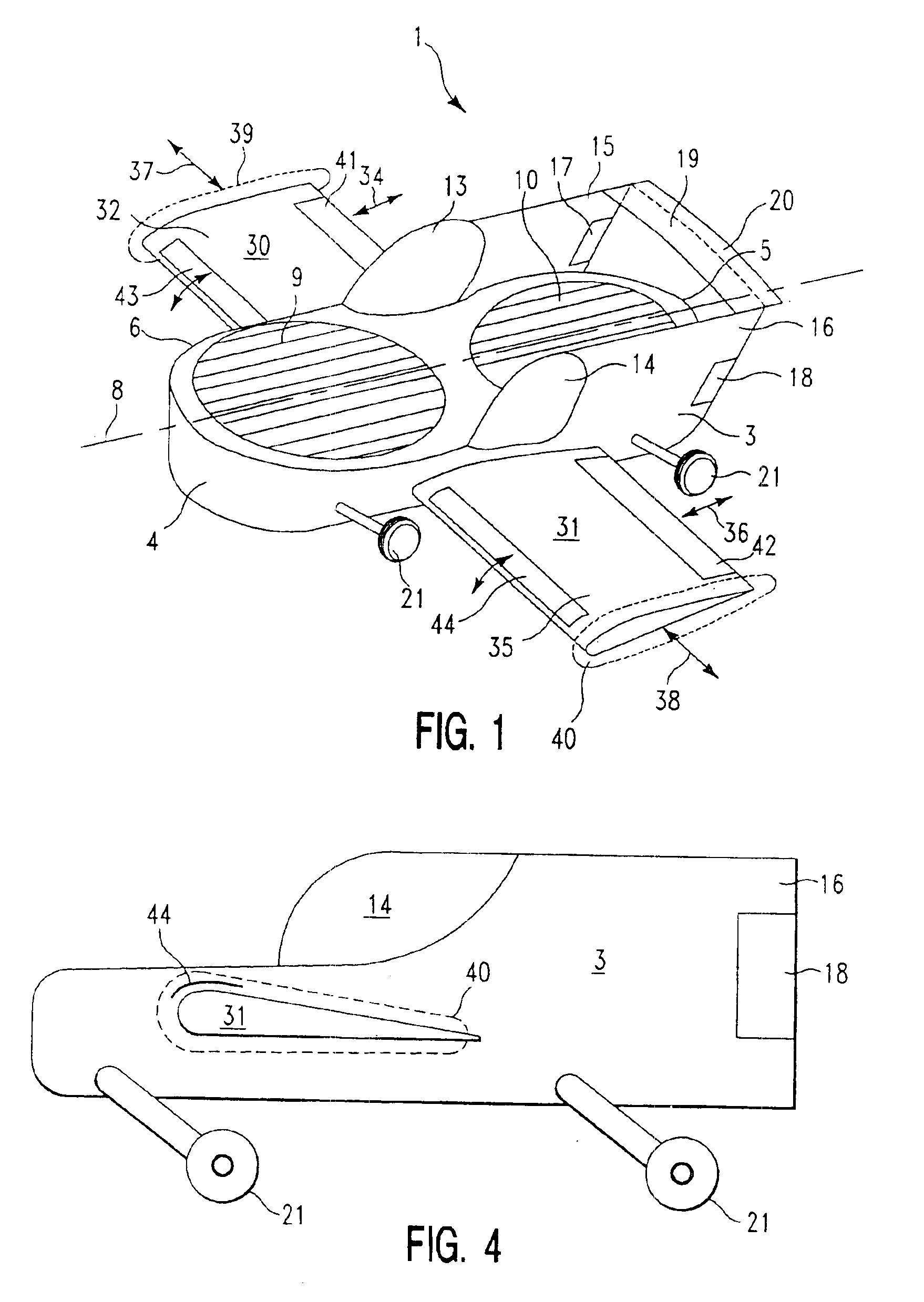
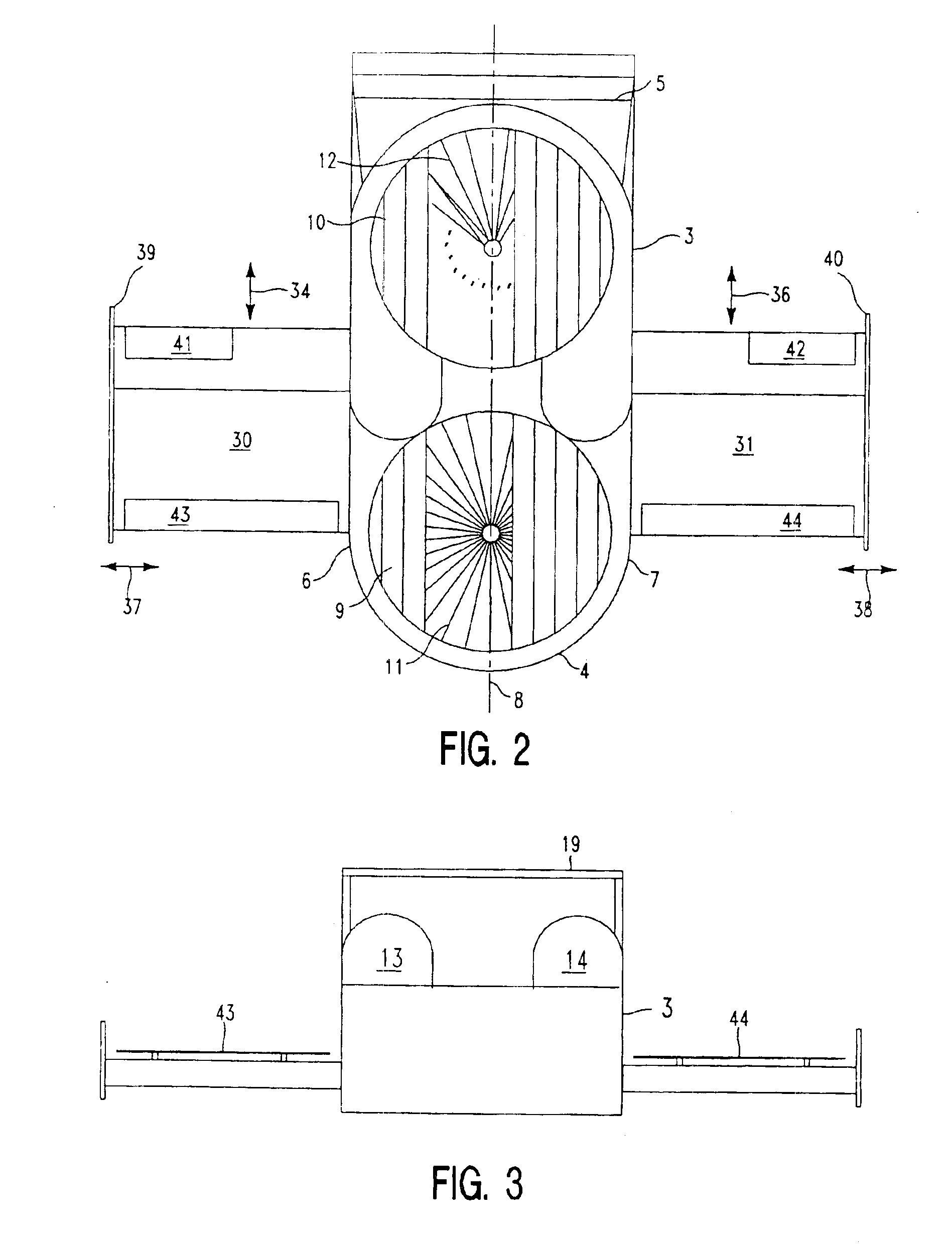
[0016]According to a preferred feature of the present invention, the wingspan of the aircraft is adjustable during flight so that footprint of the craft may be matched to the needs of the pilot. This wingspan adjustment is preferably effected by making the length of each wing telescopically extendable.
[0017]According to another preferred feature of the present invention, the width of each aircraft wing is adjustable during flight to match the wing airfoil to the speed of the aircraft. This wing width adjustment is also preferably effected by making the trailing edge of each wing telescopically extendable.

Problems solved by technology

Due to the wings, this aircraft has a relatively large “footprint”, and cannot squeeze into small spaces during flight.
This aircraft has no wings at all, so that it has an extremely small footprint and can fly through narrow passages, such as city streets.
However, due to this absence of wings, the ducted fans must generate all of the lift to maintain the aircraft aloft.
Consequently, this type of aircraft is not particularly fuel-efficient in transporting a payload from point A to point B.
This aircraft is designed for relatively high speeds (far in access of 100 MPH) and, as a result, it is not at all fuel efficient in traveling from point A to point B in the 50-100 MPH flight regime.

Method used


Image

  • VTOL personal aircraft
  • VTOL personal aircraft
  • VTOL personal aircraft

Examples


Embodiment Construction

[0025]The preferred embodiments of the present invention will now be described with reference to FIGS. 1-6 of the drawings. Identical elements in the various figures are designated with the same reference numerals.

[0026]FIGS. 1-4 illustrate the preferred embodiment of the Personal Aircraft according to the present invention. This Personal Aircraft 1 comprises a fuselage 3 having a front end 4, a rear end 5 and two lateral sides 6 and 7, respectively. The fuselage has a central longitudinal axis 8 extending from the front 4 to the rear 5 between the two lateral sides 6 and 7.

[0027]Two ducted fan units 9 and 10 are arranged in the fuselage between the front end and the rear end and between the two lateral sides for providing vertical lift. The ducted fan units each include an impeller 11 and 12, respectively, which is rotatable about a substantially vertical impeller axis. This impeller axis intersects the central longitudinal axis 8 of the aircraft.

[0028]Details about the ducted fan ...


PUM


Abstract

Personal Aircraft capable of vertical take-off and landing (“VTOL”) which comprises:(a) a fuselage having a front end, a rear end and two lateral sides, the fuselage having a central longitudinal axis extending from the front end to the rear end, between the two lateral sides;(b) at least one, and preferably two or more, ducted fans, each arranged in the fuselage between the front end and the rear end and between the two lateral sides, for providing vertical lift; and(c) at least one substantially horizontal wing attached to each side of the fuselage and extending outward with respect to the central longitudinal axis. The wings and fuselage of the aircraft are designed to provide a lift-to-drag (L / D) ratio during flight, when flying at an airspeed in the range of 50 to 100 MPH, of at least 4:1.According to a preferred feature of the present invention, the width and wingspan of the aircraft wings are adjustable during flight so that the L / D ratio and the footprint of the aircraft may be matched to the needs of the pilot.

Description

CROSS-REFERENCE TO RELATED APPLICATION[0004]The application is a continuation-in-part application of application Ser. No. 10 / 242,036 filled Sep. 11, 2002 entitled “VTOL PERSONAL AIRCRAFT”.BACKGROUND OF THE INVENTION[0005]The present invention relates to so-called “Personal Aircraft” (“PAC™”) which is capable of vertical take-off and landing (“VTOL”). Such an aircraft is operable to carry a relatively light payload (for example, 600 pounds which is the equivalent of two or three people) for short distances (for example, 250 miles) at relatively slow cruising speeds (for example, 50 to 100 MPH).[0006]A Personal Aircraft of this type is disclosed in the International Patent Publication No. WO 03 / 029075 A2, which is incorporated herein by reference. It is characterized by the use of ducted fans, instead of rotary helicopter “wings”, to generate lift while hovering. In this prior art design, a plurality of ducted fan units (each including an impeller and an engine, surrounded by a ducted...

Claims


Application Information

Patent Timeline
IPC IPC(8): B64C27/20B64C27/00B64C29/00
CPCB64C3/56B64C29/0025B64C27/20Y02T50/145Y02T50/10
Inventor MILDE, JR., KARL F.
Owner MILDE JR KARL F
Learn More