Spot welding method of high-strength steel sheets excellent in joint strength

a high-strength steel sheet and welding method technology, applied in welding electric supplies, welding apparatus, manufacturing tools, etc., can solve the problems of insufficient joint strength, high-strength steel sheet is more difficult to fit with electrodes, low ductility and toughness of weld metal, etc., to prevent the occurrence of expulsion, excellent joint strength, and high reliability

Active Publication Date: 2015-06-25
NIPPON STEEL CORP
View PDF4 Cites 26 Cited by
  • Summary
  • Abstract
  • Description
  • Claims
  • Application Information

AI Technical Summary

Benefits of technology

[0055]According to the present invention, when the high-strength steel sheets are welded by the spot welding method, by setting the pressurizing forces of the electrodes within the proper range(s) according to the sheet thickness of the steel sheets and optimally controlling the welding pattern including the pre-welding and the main welding, it is possible to secure the nugget diameter and also prevent the occurrence of expulsion while suppressing the generation of an indentation. Consequently, it is possible to form a spot-welded joint high in reliability and excellent in joint strength while maintaining good workability. Therefore, for example, in processes of manufacturing automobile parts, assembling a vehicle body, and so on, it is possible to fully enjoy merits such as fuel efficiency improvement and an emission reduction of carbon dioxide gas (CO2) owing to a weight reduction of the whole vehicle body, and their social contribution is immeasurable.

Problems solved by technology

Here, spot welding of high-strength steel sheets whose tensile strength is 780 MPa or more especially has a problem that sufficient joint strength cannot be obtained because a stress concentrates on weld metal when dislocation (load) is applied to a weld and the weld metal is low in ductility and toughness.
Further, due to their high strength, the high-strength steel sheets are more difficult to fit with electrodes than the soft steel sheets, and their contact area becomes small.
The occurrence of such expulsion has a problem of causing reduction and variation of a size of the weld metal, that is, of a joint area, leading to deterioration also of joint strength.
Further, in actual production, the fact itself that a proper current range with which a predetermined weld metal size is obtained without any occurrence of expulsion is narrow is also a problem.
The indentations (concavities) being thus too large cause a problem of lowering joint strength on the contrary even when a nugget (refer to the nugget 3 in FIG. 1 and FIG. 2) with a large diameter is obtained.
However, when the pressurizing force at the time of the welding is set low in order to suppress the generation of the indentations, the contact area between the electrodes and the steel sheets during an initial period of the welding reduces and a current density in a weld zone becomes high, so that expulsion is likely to occur.
The occurrence of this expulsion makes it difficult to secure the nugget diameter with a necessary size at the time of the spot welding, and sometimes promotes the generation of the indentations contrary to the intention.
In such a case, there are problems that deterioration and variation of joint strength occur.
Further, the expulsion sometimes adheres to the periphery of the weld zone, and when its removal is necessary, there is a problem that workability lowers.

Method used


Image

  • Spot welding method of high-strength steel sheets excellent in joint strength
  • Spot welding method of high-strength steel sheets excellent in joint strength
  • Spot welding method of high-strength steel sheets excellent in joint strength

Examples


first embodiment

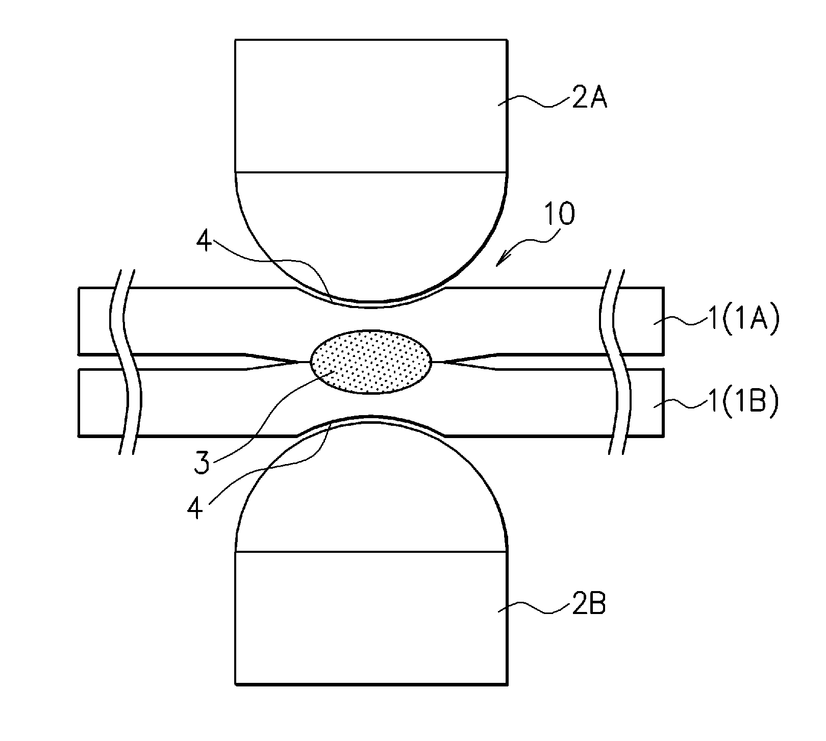
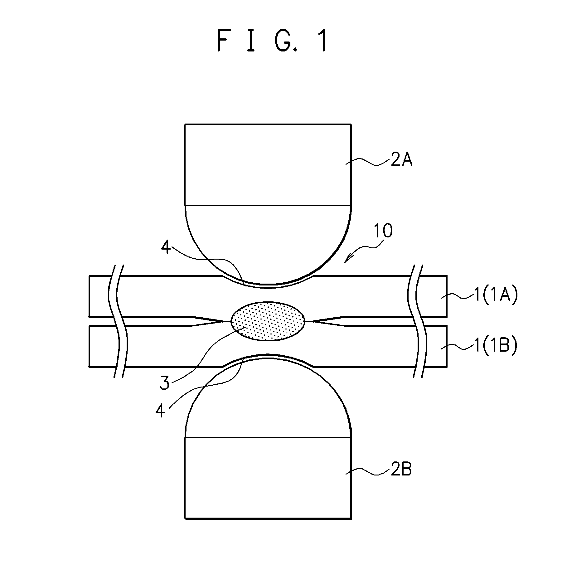
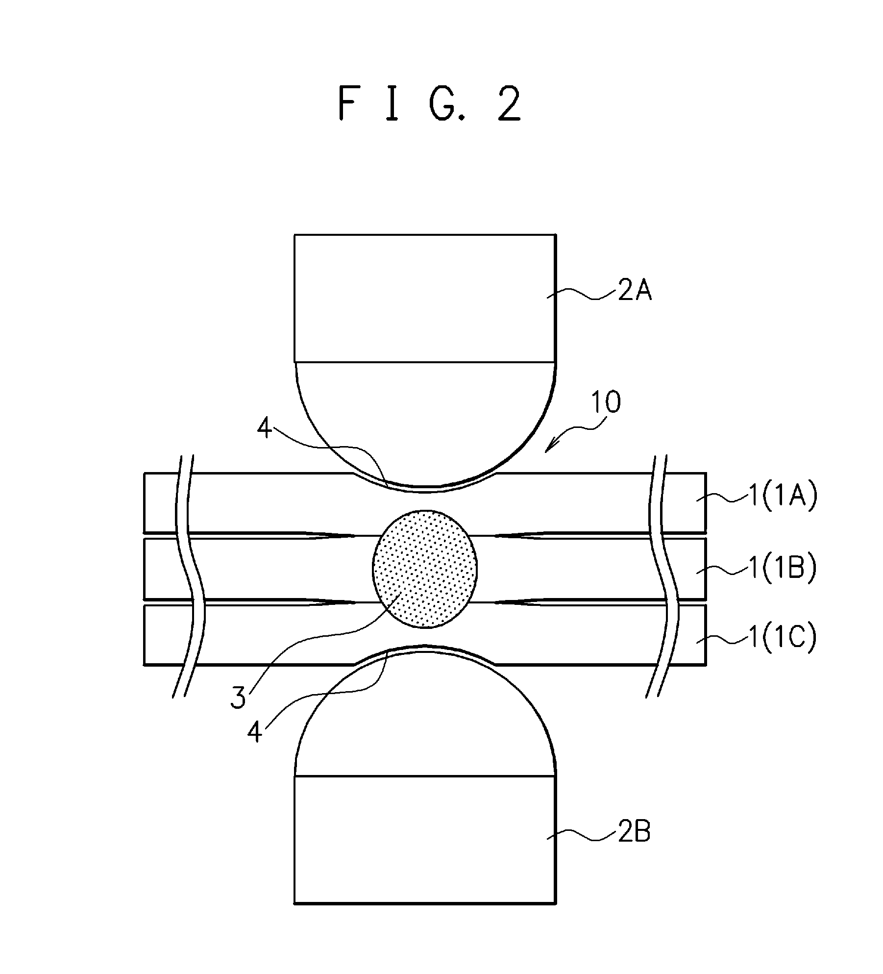
[0076]Hereinafter, a first embodiment of the spot welding method of the high-strength steel sheets according to the present invention will be described. The spot welding method of the high-strength steel sheets of the first embodiment is a method of welding two steel sheets 1A, 1B or three steel sheets 1A to 1C by resistance spot welding in order to obtain a spot-welded joint 1C illustrated in FIG. 1 and FIG. 2.

[0077]Concretely, when the two steel sheets 1A, 1B are spot-welded as illustrated in FIG. 1, these two steel sheets 1A, 1B both have tensile strength of 780 to 1850 MPa. Further, a sheet thickness ratio={the sum of sheet thicknesses of the steel sheets} / {the sheet thickness of the thinner steel sheet (when the both have the same thickness, the sheet thickness per one sheet)} is within a range of not less than 2 nor more than 5.

[0078]When the three steel sheets 1A to 1C are spot-welded as illustrated in FIG. 2, these three steel sheets 1A to 1C all have tensile strength of 780...

second embodiment

[0124]A second embodiment of the spot welding method of the high-strength steel sheets according to the present invention will be hereinafter described. Note that, in the second embodiment, its structure is described with reference to the same drawings as those in the above-described first embodiment, and the same structures will be denoted by the same reference signs and detailed description thereof will be omitted.

[0125]The spot welding method of the high-strength steel sheets of the second embodiment is a method of welding two steel sheets 1A, 1B or three steel sheets 1A to 1C by resistance spot welding as in the first embodiment, but is different from that of the above-described first embodiment in that, when at least one of gaps in the stacked steel sheets before the spot welding (hereinafter, simply referred to as the gaps) is 0.5 (mm) or more, a pressurizing force of electrodes 2A, 2B in a second welding step is changed from their pressurizing force in a first welding step.

[0...

third embodiment

[0137]A third embodiment of the spot welding method of the high-strength steel sheets according to the present invention will be hereinafter described. Note that, in the third embodiment, its structure is described with reference to the same drawings as those in the above-described first and second embodiments, and the same structures will be denoted by the same reference signs and detailed description thereof will be omitted.

[0138]The spot welding method of the high-strength steel sheets of the third embodiment is different from those of the above-described first and second embodiments in that, in obtaining a spot-welded joint 10, it has a third welding step under the following conditions after a second welding step being main welding is finished.

[0139]Concretely, the third welding step being post-welding is provided in the method described in the above first embodiment or second embodiment, after the second welding step being the main welding. In this third welding step, a welding...


PUM

PropertyMeasurementUnit
tensile strengthaaaaaaaaaa
current I3aaaaaaaaaa

Abstract

When two high-strength steel sheets (1A, 1B) whose sheet thickness ratio={the sum of sheet thicknesses of the steel sheets} / {the sheet thickness of the thinner steel sheet (when they have the same thickness, the sheet thickness per one sheet)} is within a range of not less than 2 nor more than 5 and which both have tensile strength of not less than 780 MPa nor more than 1850 MPa are stacked to be subjected to resistance spot welding, a first welding step being pre-welding with a pressurizing force P1 kN and a welding current I1 kA and a second welding step being main welding with a pressurizing force P2 kN and a welding current I2 kA are performed, the pressurizing forces P1, P2 are set to a fixed pressurizing force P=P1=P2 all through the first welding step and the second welding step and are set within a range expressed by {0.5≦P≦3.0t(1 / 3)}, where t mm is an average sheet thickness of the steel sheets (1A, 1B), the welding current I1 is set within a range of not less than 30% nor more than 90% of the welding current I2, and the second welding step is started within 0.1 s after the first welding step is finished.

Description

TECHNICAL FIELD[0001]The present invention relates to a spot welding method of high-strength steel sheets excellent in joint strength, for forming a weld by spot welding in, for example, processes of manufacturing automobile parts, assembling a vehicle body, and so on.BACKGROUND ART[0002]In recent years, in an automobile field, there has been an increasing need for using high-strength steel sheets for a vehicle body, parts, and so on in order to reduce the weight of the vehicle body with the aim of improving fuel efficiency and reducing an emission of carbon dioxide gas (CO2) and to improve collision safety. Meanwhile, in processes of assembling the vehicle body, attaching the parts, and so on, spot welding is mainly used.[0003]As important properties of a joint formed by the spot welding (hereinafter, referred to as a spot-welded joint), tensile strength and fatigue strength can be cited, but what is important first is tensile strength. Tensile strength of the spot-welded joint inc...

Claims


Application Information

Patent Timeline
Patent Type & Authority Applications(United States)
IPC IPC(8): B23K11/11B23K11/24B23K11/16
CPCB23K11/115B23K11/241B23K11/16
Inventor FURUSAKO, SEIJIOIKAWA, HATSUHIKOMIYAZAKI, YASUNOBU
Owner NIPPON STEEL CORP
Why Eureka
Try Eureka