Vertical takeoff and landing aircraft

a vertical takeoff and landing and aircraft technology, applied in vertical landing/take-off aircraft, aircraft navigation control, machines/engines, etc., can solve the problems of high cost, difficult to construct an airport near urban areas, and high cost for citizens in small or medium-sized cities, and achieves stable maneuverability and superiority.

Inactive Publication Date: 2005-05-17
MITSUBISHI HEAVY IND LTD
View PDF6 Cites 181 Cited by
  • Summary
  • Abstract
  • Description
  • Claims
  • Application Information

AI Technical Summary

Benefits of technology

[0016]Therefore, the object of the present invention is to provide a vertical takeoff and landing aircraft with superior, stable maneuverability, having common fans for cruising and lifting, and the thrust from the fans being capable of being directed to all directions.

Problems solved by technology

However, it is difficult to construct an airport near urban areas because a long runway and vast air space are required for a conventional jet liner to make safe takeoff and landing.
It is especially difficult for a small or medium size city, because the construction of an airport invalues large expense, and for a large city also it is difficult, because of the difficulty of securing a vast area, the problem of the high noise produced by jet liners, and safety problems.
Therefore, even with a large city the airport is constructed to be remote from the city, and it is necessary for citizens dwelling in a small or medium size city to go to an airport located near an urban area, thus expending a lot of time.
Accordingly, it is becoming expensive for citizens in small or medium size cities, and also for citizens in large cities, to access the airport, and there may occur the case where it saves more time and expense to travel overland than by air.
However, the weight carried by a helicopter is limited and its speed is also limited, so it is not a satisfying means for solving the problem mentioned above.
However, the engines of the tilt-rotor type and tilt-wing type VTOL aircraft are large and they are necessarily mounted at positions apart from the center of gravity of the airframe, so that the moment of inertia becomes large, resulting in poor mobility.
Further, in the case of the 2-fan type, the diameter of the fan is large, and a gliding landing is impossible.
Therefore, in case of a fault in the tilting mechanism, landing is impossible, and at the same time, stable maneuverability cannot be ensured because of 2-point support.
These are drawbacks of these types and induce safety problems.
Particularly with the tilt-wing type, the size of the tilting mechanism has to be large and the attitude control mechanism (fans, etc. at the front and rear of the airframe) is complicated, which generally results in increased weight of the airframe.
As the fan and turbine are located on the same axis, the core engine must be located along the direction of the fan and the mounting position of the turbofan engine to the aircraft is restricted, resulting in a low degree of design flexibility.
However, the VTOL aircraft of prior art 1 or 2 has separate fans for cruising and lifting as shown in FIG. 15, so during lifting, the weight of the cruise fans 164 is useless and excess weight, and when cruising, the weight of the lift fans 162 is useless and excess weight.
Further, as the lift fans 162 are fixed to the fixed wings, fine adjustments in hovering are difficult.

Method used


Image

  • Vertical takeoff and landing aircraft
  • Vertical takeoff and landing aircraft
  • Vertical takeoff and landing aircraft

Examples


Embodiment Construction

[0046]A preferred embodiment of the present invention will now be detailed with reference to the accompanying drawings. It is intended, however, that unless particularly specified, dimensions, materials, relative positions and so forth of the constituent parts in the embodiments shall be interpreted as illustrative only not as limitative of the scope of the present invention.

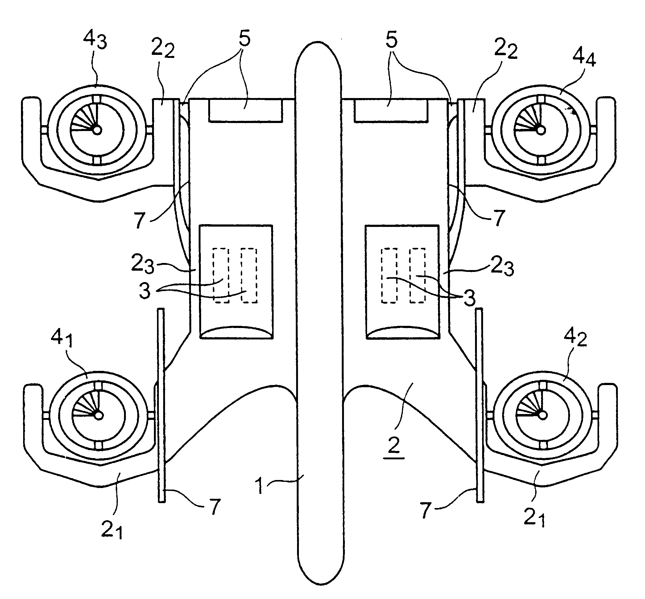
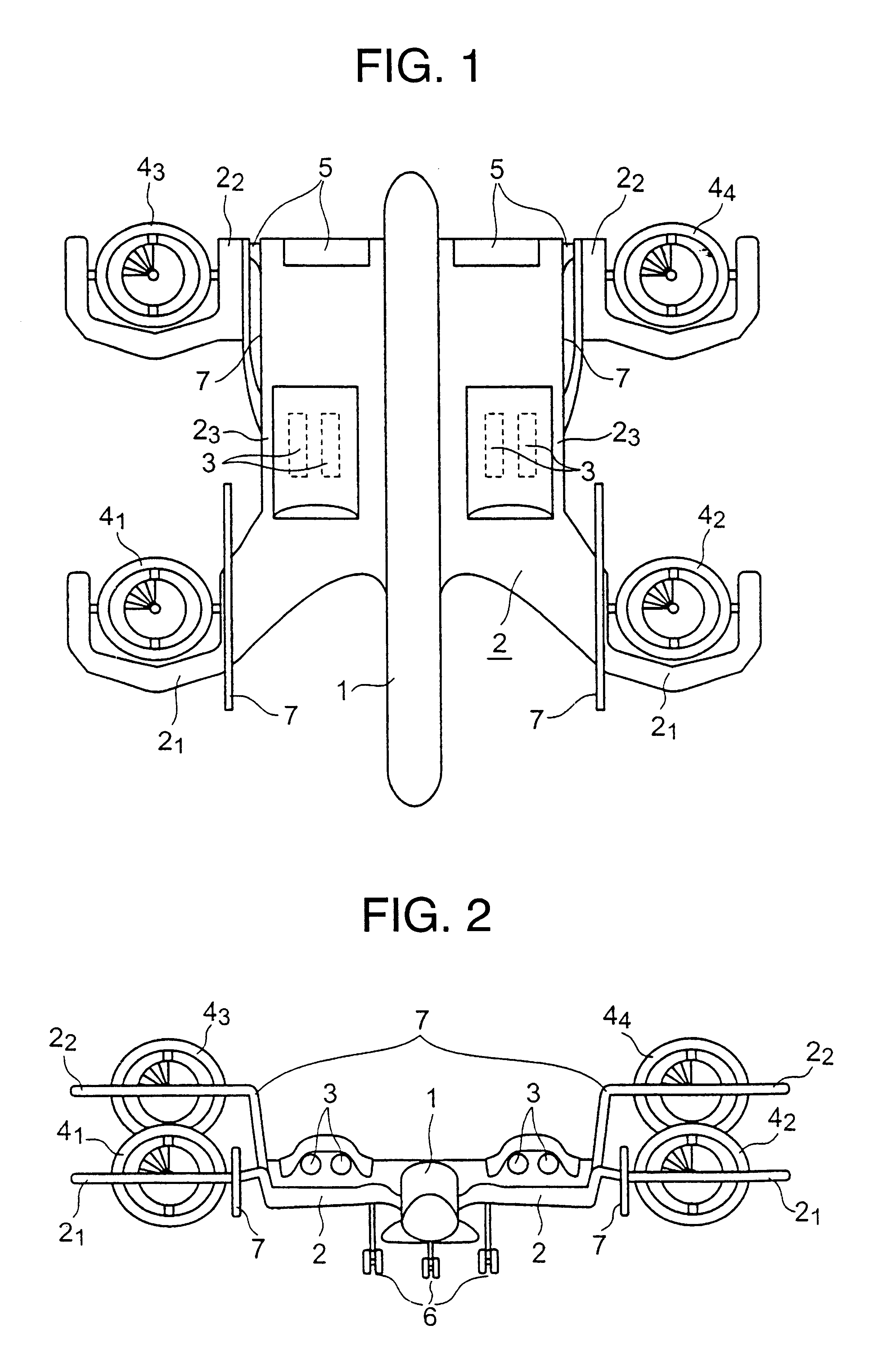
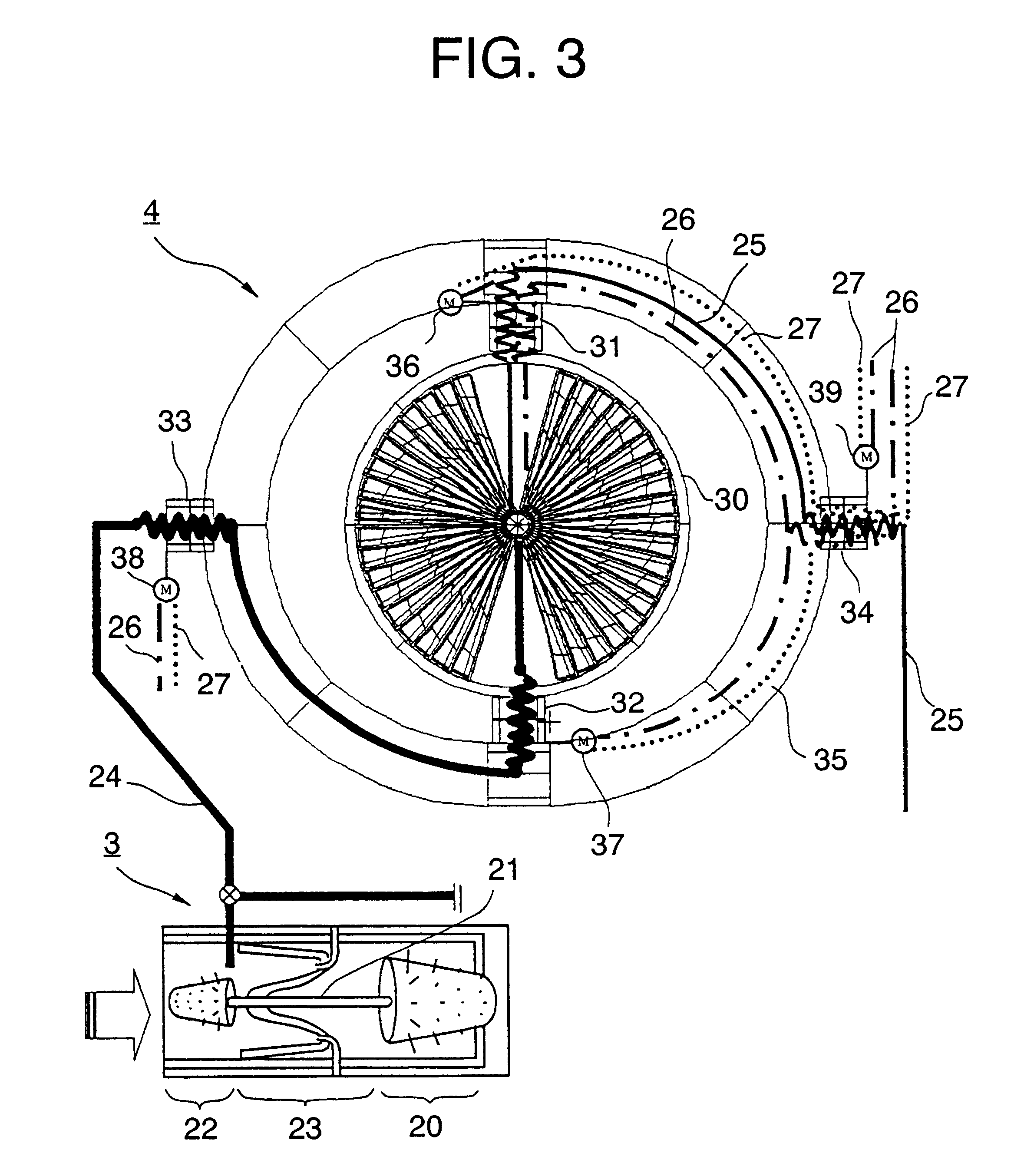
[0047]FIG. 1 is a top plan view of an embodiment of the VTOL aircraft according to the present invention. FIG. 2 is a front elevation when the tilt fan engines composing propulsion devices are tilted. FIG. 3 is a schematic illustration showing the construction of the core engine and tilt fan engine of the turbo-fan engine with a separate core engine. FIG. 4(A) and FIG. 4(B) are illustrations for explaining the fan engine. FIG. 5 to FIG. 12 are schematic illustrations explaining various states of hovering, cruising, and so on of the VTOL aircraft according to the present invention, and FIG. 13 and FIG. 14 are dra...


PUM


Abstract

A vertical takeoff and landing (VTOL) aircraft is superior in maneuverability, safety, and mobility. The aircraft has turbofan engines with separate core engines having fan engines used commonly for cruising and lifting up. The thrust from the fan engines can be directed to all directions by supporting the fan engines of the turbofan engines with separate core engines with biaxial support so that the fan engines are rotatable in the direction of pitching and rolling. The fan engines are mounted on both sides of each of front and rear sings. With this construction, the VTOL aircraft can cruise and hover by tilting the fan engines about the two axes while using the fan engines commonly for cruising and hovering.

Description

BACKGROUND OF THE INVENTION[0001]1. Field of the Invention[0002]The present invention relates to a vertical takeoff and landing (VTOL) aircraft, specifically to a vertical takeoff and landing aircraft consisting of core engines, turbofan engines consisting of a fan engine supported in biaxial support and supplied with high-pressure air from the core engine, and left / right front wings and left / right rear wings mounted with the fan engine on both left and right sides of both wings, wherein hovering and cruising are possible with the same propulsion units.[0003]2. Description of the Related Art[0004]Construction of airports near urban areas is desired to meet the demand for the movement between cities in a short time. However, it is difficult to construct an airport near urban areas because a long runway and vast air space are required for a conventional jet liner to make safe takeoff and landing. It is especially difficult for a small or medium size city, because the construction of a...

Claims


Application Information

Patent Timeline
Patent Type & Authority Patents(United States)
IPC IPC(8): B64C11/00B64C15/00B64C15/12B64D35/00B64C29/00F02K3/00F02K3/02F02K3/12
CPCB64C11/001B64C15/12B64C29/0033B64D35/00F02K3/025B64C29/0075Y02T50/671Y02T50/60
Inventor KAWAI, HIDEHARU
Owner MITSUBISHI HEAVY IND LTD
Why Eureka
Try Eureka