Modular cable support apparatus, method, and system

Inactive Publication Date: 2005-05-17
PREFORMED LINE PROD CO
View PDF39 Cites 116 Cited by
  • Summary
  • Abstract
  • Description
  • Claims
  • Application Information

AI Technical Summary

Benefits of technology

[0013]One advantage of the present invention resides in its ability to arrange a plurality of cable supports in a staggered-height fashion to allow greater clearance between adjoining cables thereby reducing the likelihood of cable impingement.
[0014]Another advantage of the present invention resides in an adaptable hinge which improves clamping force uniformity in the presence of variations in the clamp tightening and/or in the presence of winds o

Problems solved by technology

Although aerial cables are relatively safe from ground-based sources of damage, they are subject to environmental wear and damage, principally due to winds.
Well known in the art are problems caused by aeolian vibration which is a high frequency, low amplitude vibration caused by laminar winds passing across the line, as well as “galloping” which is a low frequency, high amplitude wind-induced cable motion.
Wind action can produce cable damage in the form of abrasion, wear, and fatigue, especially at the suspension points where cable support devices inherently form mechanical stress points in the cable.
The potential for such damage can be increased by excessive clamping force, by inadequate clamping force which allows the cable to slide within the clamp, or by a

Method used


Image

  • Modular cable support apparatus, method, and system
  • Modular cable support apparatus, method, and system
  • Modular cable support apparatus, method, and system

Examples


Embodiment Construction

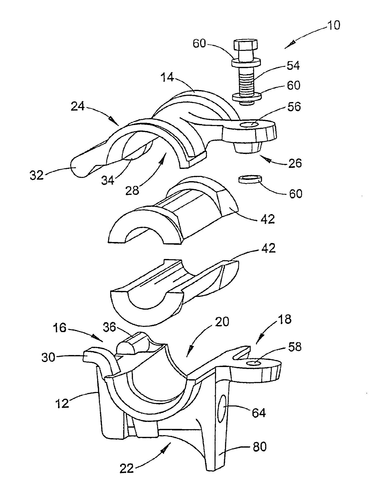
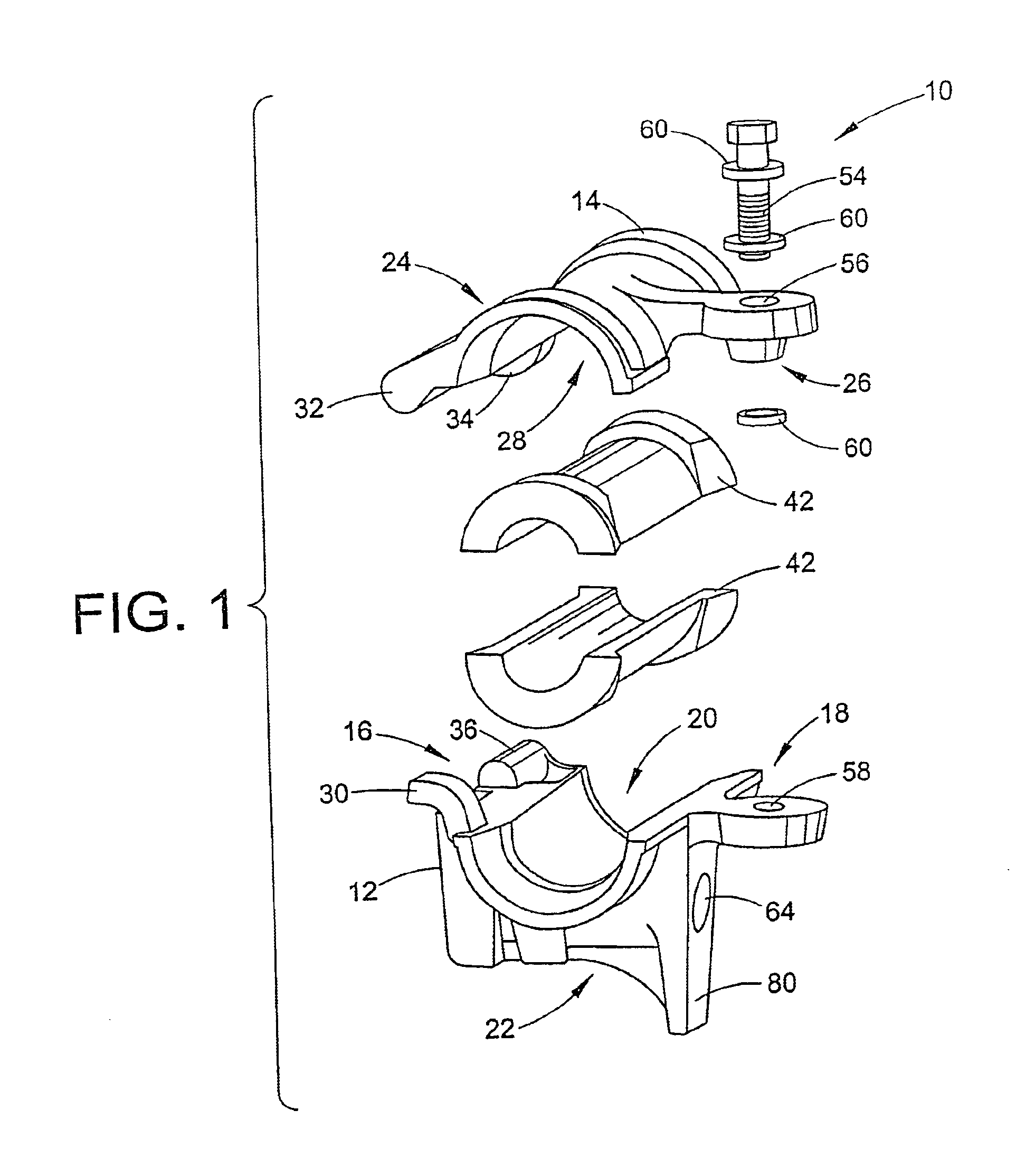
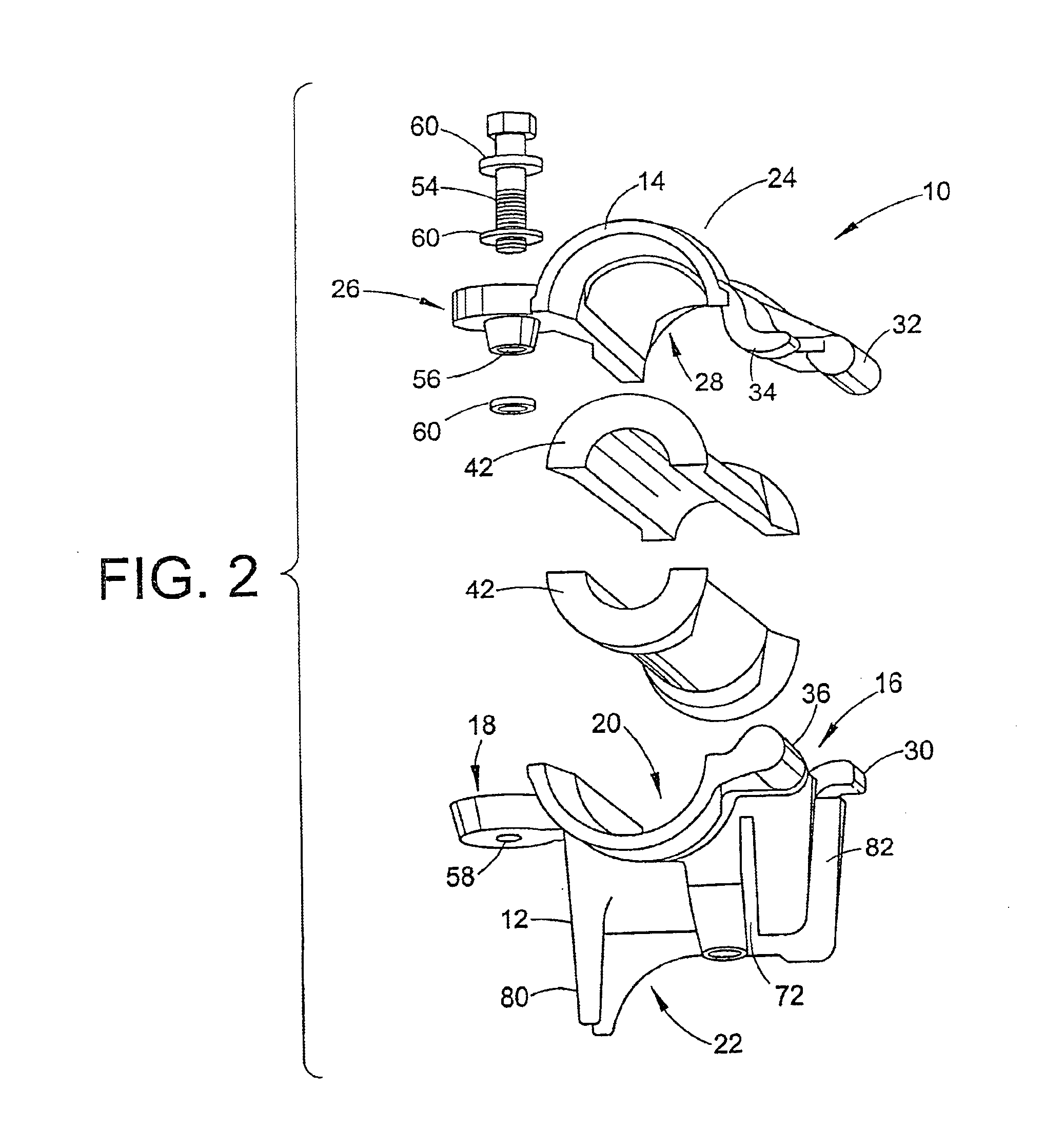
[0029]With reference to FIGS. 1 and 2, a cable support 10 in accordance with a first preferred embodiment of the invention includes a lower clamp base 12 and upper clamp keeper 14. The clamp base 12 includes a hinge region 16, a tightening region 18, and a cable channel region 20 arranged between the hinge and tightening regions 16, 18. The clamp base 12 also includes an interconnecting structure 22 for adapting the base for connection to a pole or other structure and for adapting a plurality of bases 12 to be interconnected as will be described in greater detail below. The clamp keeper 14 includes a hinge region 24, a tightening region 26, and a cable channel region 28 arranged between the hinge and tightening regions 24, 26.

[0030]With continuing reference to FIGS. 1 and 2 and with further reference to FIG. 3, the clamp base 12 and the clamp keeper 14 are adapted to selectively cooperatively hingedly connect via the hinge regions 16, 24. The clamp base hinge region 16 includes a cu...


PUM


Abstract

A cable support system includes a plurality of first components (12) and a plurality of second components (14). Each first component (12) has a hinge edge (16), a tightening region (18) disposed on an opposite side from the hinge edge (16), a cable channel (20) arranged between the hinge edge (16) and the tightening region (18), and an interconnecting structure (22). Each second component (14) has a hinge edge (24), a tightening region (26) disposed on an opposite side from the hinge edge (24), and a cable channel (28) arranged between the hinge edge (24) and the tightening region (26). A first cable support device (10) is constructable by hingeably combining selected first and second components (12, 14) via the hinge edges (16, 24). A second cable support device (100) is constructable by hingeably combining selected two second components (14) via the hinge edges (24).

Description

BACKGROUND OF THE INVENTION[0001]The present invention relates to the cable support arts. It particularly relates to supporting and suspending cables from poles or other overhead support structures, and will be described with particular reference thereto. The invention will also find application in conjunction with various types of cables such as telephone cables, cables for “cable” television, high tension wires, fiber optical cables, and optical ground wires (OPGW's). In addition to suspending cables from poles and the like, the present invention is operative with flat support surfaces and, accordingly finds use in supporting cables and other objects in vault and other similar or related applications.[0002]Power lines, telephone transmission lines, and other cables are frequently suspended aerially from a plurality of poles or other support structures. An aerial cable arrangement is relatively simple and flexible, and has a limited ground footprint that frequently permits space su...

Claims


Application Information

Patent Timeline
IPC IPC(8): H02G7/00H02G7/05
CPCH02G7/053
Inventor PISCZAK, PHILIP J.
Owner PREFORMED LINE PROD CO
Why Eureka
Try Eureka