Method for preparing a solid golf ball

Inactive Publication Date: 2005-05-17
BRIDGESTONE SPORTS
View PDF6 Cites 5 Cited by
  • Summary
  • Abstract
  • Description
  • Claims
  • Application Information

AI Technical Summary

Benefits of technology

[0004]In view of the foregoing, the present invention has been made, and an object of the present invention is to provide a solid golf ball produced by forming a thin urethane cover around a core made from a rubb

Problems solved by technology

The injection molding for forming the urethane cover, however, has an inconvenience that the urethane cover material can be relatively easily injection-molded around a relatively smooth surface of a core made from an ionomer resin or a polyester elastomer, but is difficult to be thinly injection-molded around a rough surface of a core made from a rubber material.
1.9 mm or more) around a core made from a rubber material by injection molding, but it is difficult to form an urethane cover having a small thickness (for example, 0.8 mm or less) around a core made from a rubber material by injection molding.
To be more specifi

Method used


Image

  • Method for preparing a solid golf ball
  • Method for preparing a solid golf ball
  • Method for preparing a solid golf ball

Examples


Example

EXAMPLE

[0064]The present invention will be described in more detail with reference to the following examples, although not limited thereto.

Example

Examples 1 to 5 and Comparative Examples 1 to 3

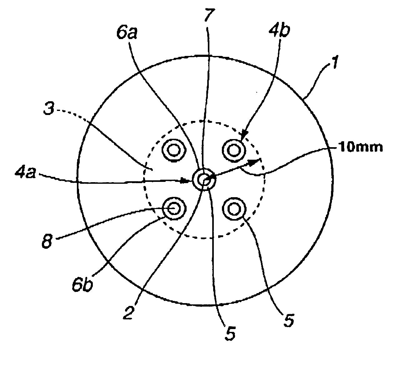
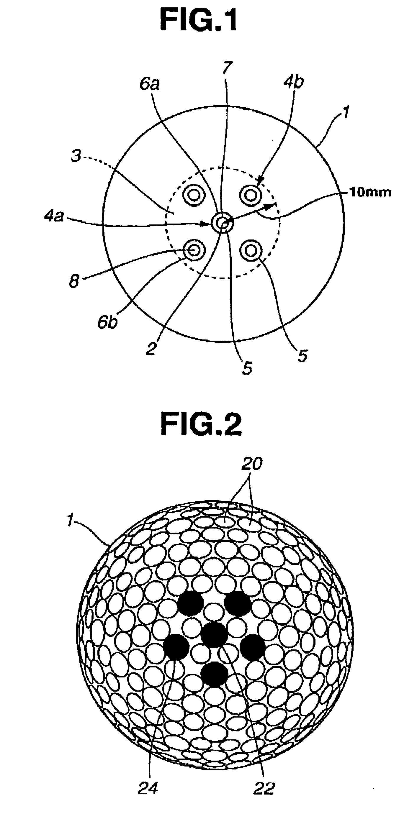
[0065]Cores shown in Table 4 were produced by using rubber compositions shown in Table 1. It is to be noted that in Comparative Example 3, an intermediate layer made from an ionomer resin was formed around the core. Each of cover materials shown in Table 3 was formed around the corresponding one of the cores thus prepared by injection molding using a mold having a specification shown in Table 2. To be more specific, after the core was set in the mold, the cover material melted at 225° C. was injection-molded in a cavity of the mold at an injection rate determined by three-step injection speeds (first speed: 1.5×105 mm3 / sec, second speed: 1.0×105 mm3 / sec, and third speed; 5.0×104 mm3 / sec), to obtain a golf ball having a dimple arrangement (total number of dimples: 432) shown in FIG. 2. In this injection molding, the holding pressure was set to 2 MPa, and core supporting pins were pulled out when the cover material reached the supporting ...

Example

Examples 6 to 8 and Comparative Examples 4 and 5

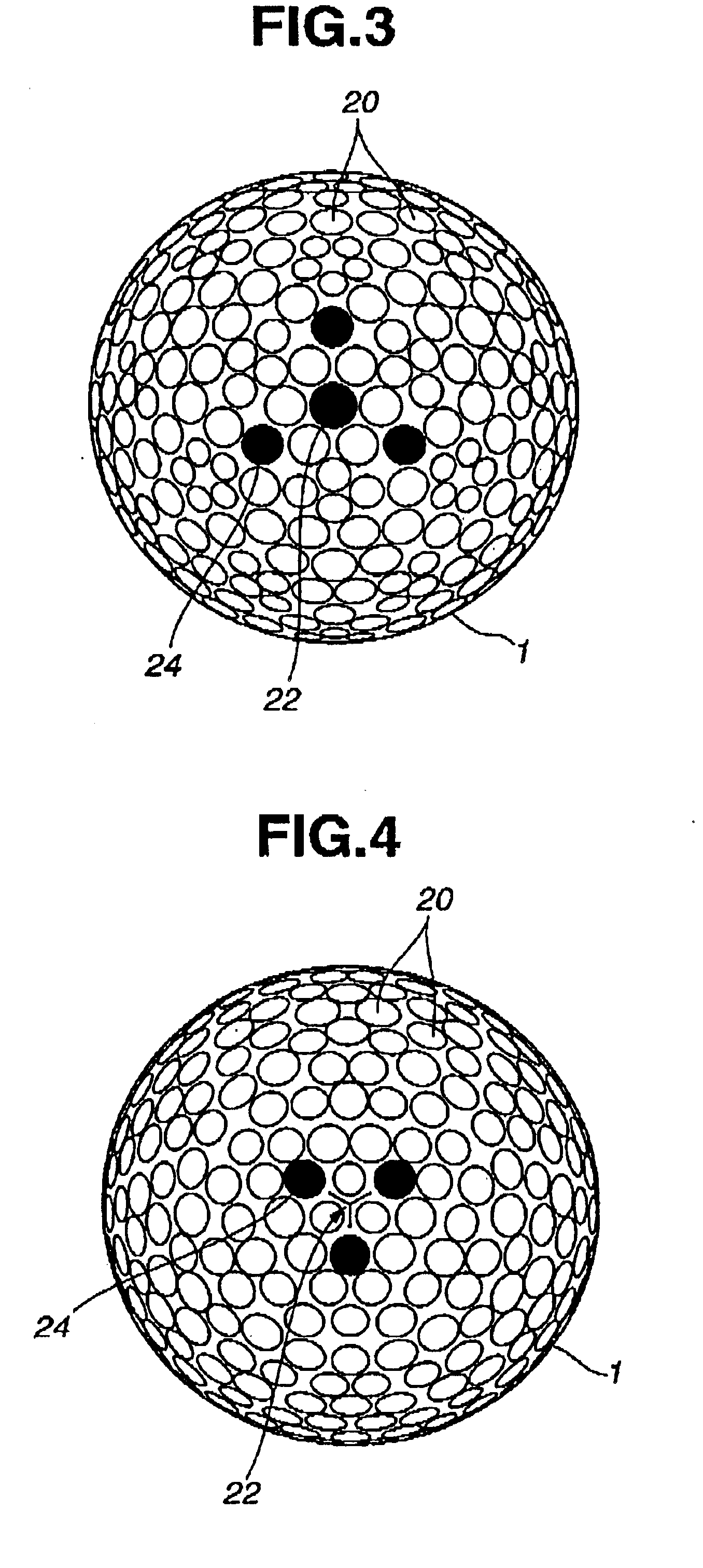
[0085]Golf balls In Examples 6 to 8 and Comparative Examples 4 and 5 were obtained in the same manner as that used In Example 1, except for the use of molds for injection molding shown in Table 5 and dimple arrangements shown in FIGS. 3 to 7 for Examples 6 to 8 and Comparative Examples 4 and 5, respectively. The degree of air entrainment for each of the golf balls was evaluated by the following method. The results are shown in Table 5.

Degree of Air Entrainment

[0086]The degree of air entrainment of each of the golf balls was evaluated on the basis of visual observation of a streak having a length of 1 mm or more or a depression having an area of 1 mm2 or more due to air on the surface of the cover.

[0087]TABLE 5ComparativeExampleExample167845Dimple arrangementFIG. 2FIG. 3FIG. 4FIG. 5FIG. 6FIG. 7Shape of dedicated airCircularCircularY-shapeCircularCircularCircularvent pin holeshapeshapeshapeshapeshapeDiameter (mm) of dedicated4.164.044.16...


PUM

PropertyMeasurementUnit
Weightaaaaaaaaaa
Weightaaaaaaaaaa
Lengthaaaaaaaaaa

Abstract

A solid golf ball includes a core formed from a rubber composition and a cover directly covering the core. The cover is formed from a cover material mainly containing a thermoplastic urethane resin by injection molding using a mold composed of upper and lower mold halves. The core has a hardness, expressed by a deflection measured under an applied load of 5 kg to 130 kg, in a range of 2.0 mm or more. The cover has a thickness in a range of 0.9 mm to 1.7 mm. Assuming that a parting plane of the upper and lower mold halves is taken as an equator, each of the upper and lower mold halves has air vent portions in a region within a radius of 10 mm, measured as that projected on the equator plane, from a pole of the mold half. The total length of gaps of the air vent portions formed in the upper and lower mold halves is in a range of 90 mm or more. The width of each of the gaps of the air vent portions is in a range of 0.01 to 0.08 mm. The total area, measured as that projected on the equator plane, of the gaps of the air vent portions formed in the upper and lower mold halves is in a range of 1 to 5 mm2. The solid golf ball exhibits a high resilience and excellent controllability and durability while keeping a soft feel when hit with a putter, and is particularly characterized in that even a thin cover can be stably formed around the core by injection molding,

Description

BACKGROUND OF THE INVENTION[0001]The present invention relates to a solid golf ball produced by injection-molding a thermoplastic urethane resin relatively thinly around a core made from a rubber material.[0002]Golf balls using covers made from thermoplastic urethane resins (hereinafter, often referred to simply “urethane covers”) have been proposed. In the process of producing such a golf ball, it is recommended to form the urethane cover by injection molding from the viewpoint of easy molding. The injection molding for forming the urethane cover, however, has an inconvenience that the urethane cover material can be relatively easily injection-molded around a relatively smooth surface of a core made from an ionomer resin or a polyester elastomer, but is difficult to be thinly injection-molded around a rough surface of a core made from a rubber material. For example, it is easy to form an urethane cover having a relatively large thickness (for example. 1.9 mm or more) around a core ...

Claims


Application Information

Patent Timeline
IPC IPC(8): A63B37/00A63B37/12A63B37/04A63B45/00
CPCA63B37/0003A63B37/0033A63B37/12A63B37/0065A63B37/0062
Inventor SHIMOSAKA, HIROTAKA
Owner BRIDGESTONE SPORTS
Why Eureka
Try Eureka