Angle-adjustable bone screw and fixation device

a fixation device and screw technology, applied in the field of orthopaedic fixation devices, can solve the problems of bone fixation, unsuitable for taking up forces, and only allowing and achieve the effect of preventing the blockage of the ball-joint-type connection

Inactive Publication Date: 2005-05-17
SYNTHES USA
View PDF53 Cites 115 Cited by
  • Summary
  • Abstract
  • Description
  • Claims
  • Application Information

AI Technical Summary

Benefits of technology

[0041]Advantageously, the invention may provide a bore for receiving a bone screw with a collar which is designed to abut a concave portion of the bore. Further, a linear contact may be obtained which, upon fixation of the device, leads to a secure connection between bone screw and fixation body. In the case of a deformable bore wall, a form-fit connection between...

Problems solved by technology

However, because of the often inexactly matching spherical surfaces on the bone screw and in the anchoring element, such a blockable ball-joint-type connectio...

Method used


Image

  • Angle-adjustable bone screw and fixation device
  • Angle-adjustable bone screw and fixation device
  • Angle-adjustable bone screw and fixation device

Examples


Embodiment Construction

[0051]For convenience, the same or equivalent elements in the various embodiments of the invention illustrated in the drawings have been identified with the same reference numerals. Further, in the description that follows, any reference to either orientation or direction is intended primarily for the convenience of description and is not intended in any way to limit the scope of the present invention thereto.

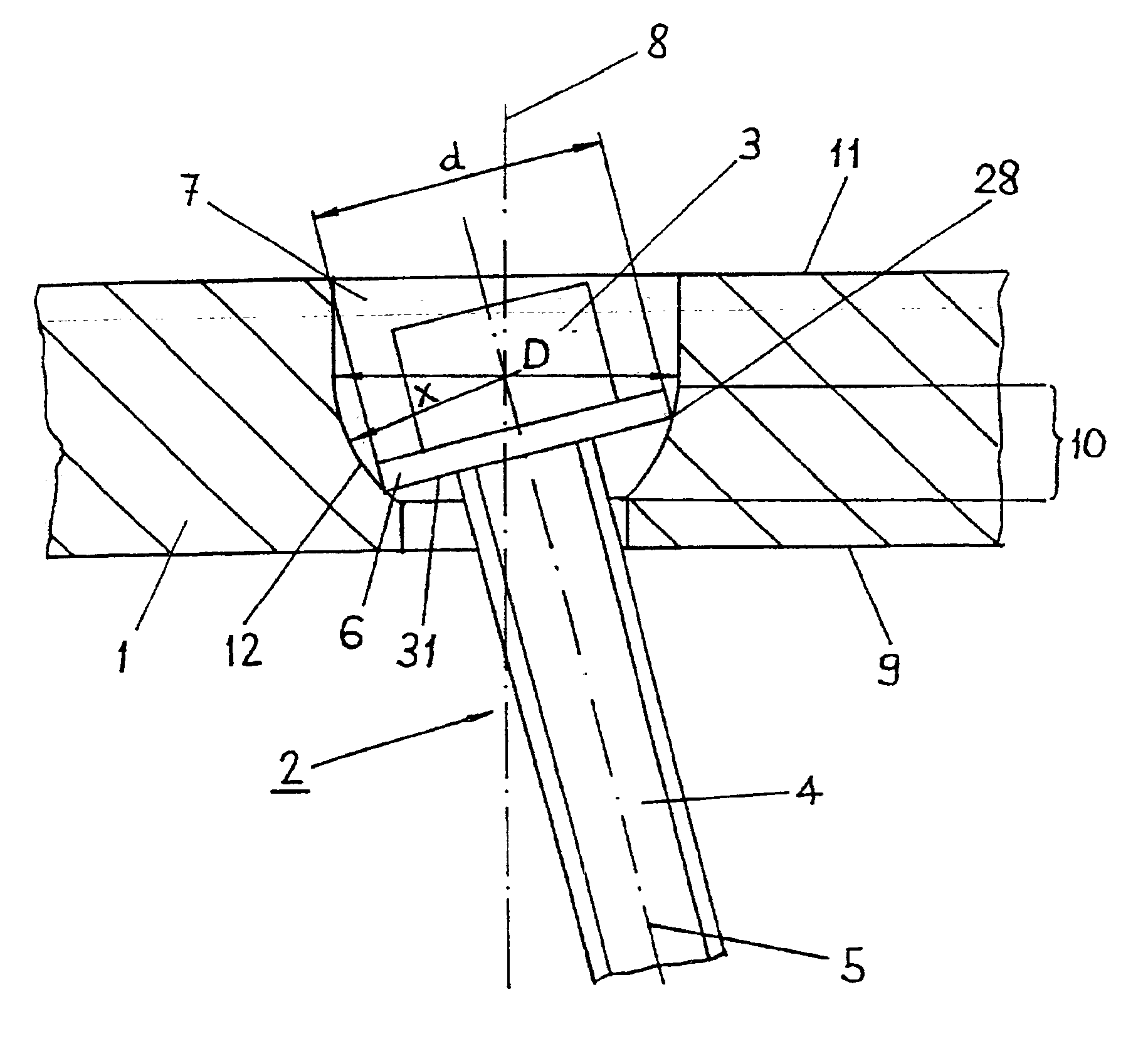
[0052]Referring to FIG. 1, a part of a bone fixation body (or receiving member) 1 is shown together with a bone screw 2 according to one exemplary embodiment of the device of the present invention. In this embodiment, the bone fixation body 1 is designed as a bone plate and has an underside 9 toward the screw shank and an upper side 11 toward the screw head. The underside 9 is intended to bear on the bone when the bone plate is screwed tight. The bone screw 2 is received in the bone fixation body 1 in a bore 7, which has a central axis 8. The central axis 8 passes through bone ...


PUM


Abstract

The invention is related to a bone screw and a device for osteosynthetic fixation. The bone screw includes a head, a shank, and a collar disposed therebetween. A plate or bone fixation assembly may be provided with at least one bore configured and dimensioned to receive such a bone screw, the bore including a tapered wall portion. When the screw is received in the bore and the collar abuts the tapered wall portion, the screw may be disposed at a variety of angles with respect to the plate and fixed at a selected angle.

Description

CROSS-REFERENCE TO RELATED APPLICATIONS[0001]This application is a continuation of the U.S. national stage designation of copending International Patent Application PCT / CH99 / 00302, filed Jul. 7, 1999, the entire content of which is expressly incorporated herein by reference thereto.FIELD OF THE INVENTION[0002]The present invention relates generally to orthopaedic fixation devices, and in particular to a fixation system for vertebral bodies.BACKGROUND OF THE INVENTION[0003]Various devices for internal fixation of bone fragments in a human or animal body are known in the prior art. In the case of internal fixation of the spinal column or of parts of the spinal column, such devices often essentially comprise pedicle screws which are anchored by means of threads into the pedicles of the individual vertebrae to be joined, and one or more longitudinal supports which extend in the direction of the spinal column and have to be connected securely to the pedicle screws. To achieve stable anch...

Claims


Application Information

Patent Timeline
IPC IPC(8): A61B17/70A61B17/80A61B17/68A61B17/58A61F2/28
CPCA61B17/8042A61B17/7037A61B17/7032
Inventor FRIGG, ROBERTFERUS, ROBERT
Owner SYNTHES USA
Why Eureka
Try Eureka