Ferroelectric non-volatile logic elements

a non-volatile, logic element technology, applied in the field of logic elements, can solve the problem that the only useful means of interrogation and sensing are not represented, and achieve the effect of optimizing sensing performance and easy translation into device layou

Inactive Publication Date: 2005-05-17
MONTEREY RES LLC
View PDF30 Cites 403 Cited by
  • Summary
  • Abstract
  • Description
  • Claims
  • Application Information

AI Technical Summary

Benefits of technology

[0008]According to the present invention, the following description details the methodology used to render logic elements non-volatile through the strategic addition of ferroelectric capacitors and supporting devices. In each case, the building blocks of a cross-coupled sense amplifier are identified within the logic element and the basic cell is modified and / or optimized for sensing performance. More so than the fundamental logic elements involved, memory sense amplifiers require carefully balanced layout to properly detect the memory state over the lifetime of the part. Because of this, care is taken to create symmetry within the design that is easily translated into device layout.

Problems solved by technology

Where timing diagrams are shown, they may not represent the only useful means of interrogation and sensing.

Method used


Image

  • Ferroelectric non-volatile logic elements
  • Ferroelectric non-volatile logic elements
  • Ferroelectric non-volatile logic elements

Examples


Embodiment Construction

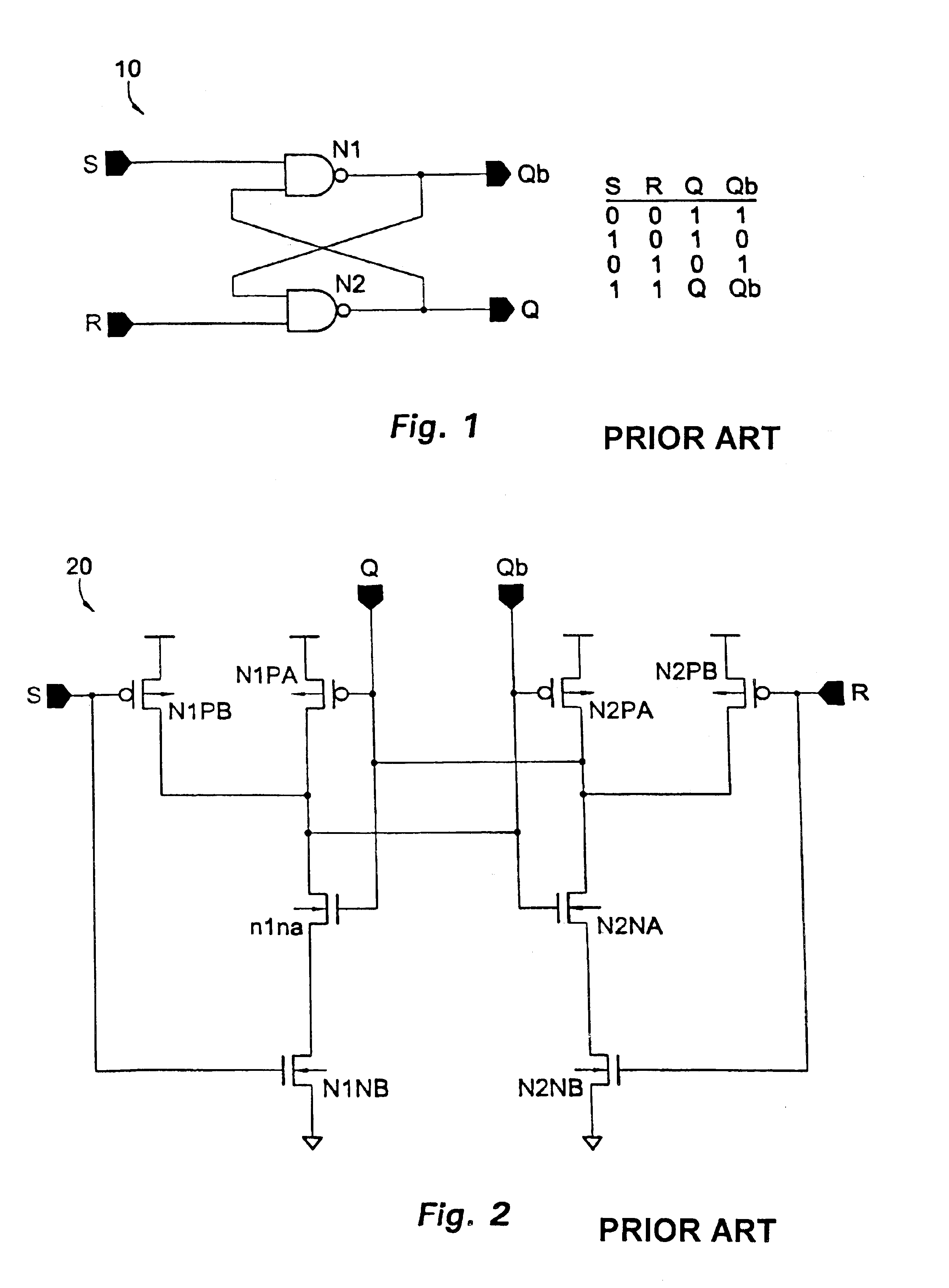
[0084]Referring now to FIG. 1, a volatile SR flip-flop 10 is shown that is converted into a non-volatile SR flip-flop with the addition of ferroelectric capacitors and supporting devices. The resulting device maintains the functionality of the SR flip-flop 10 and inherits the non-volatility of ferroelectric memories. FIG. 1 therefore shows the standard gate representation of a NAND-based SR flip-flop 10 including NAND gates N1 and N2 and the corresponding truth table.

[0085]Referring now to FIG. 2, one possible CMOS implementation 20 of flip-flop 10 is shown. NAND gate N1 from FIG. 1 is implemented by PMOS transistors N1PA and N1PB and series-connected NMOS transistors N1NA and N1NB. Similarly, NAND gate N2 from FIG. 1 is implemented by PMOS transistors N2PA and N2PB and series-connected NMOS transistors N2NA and N2NB.

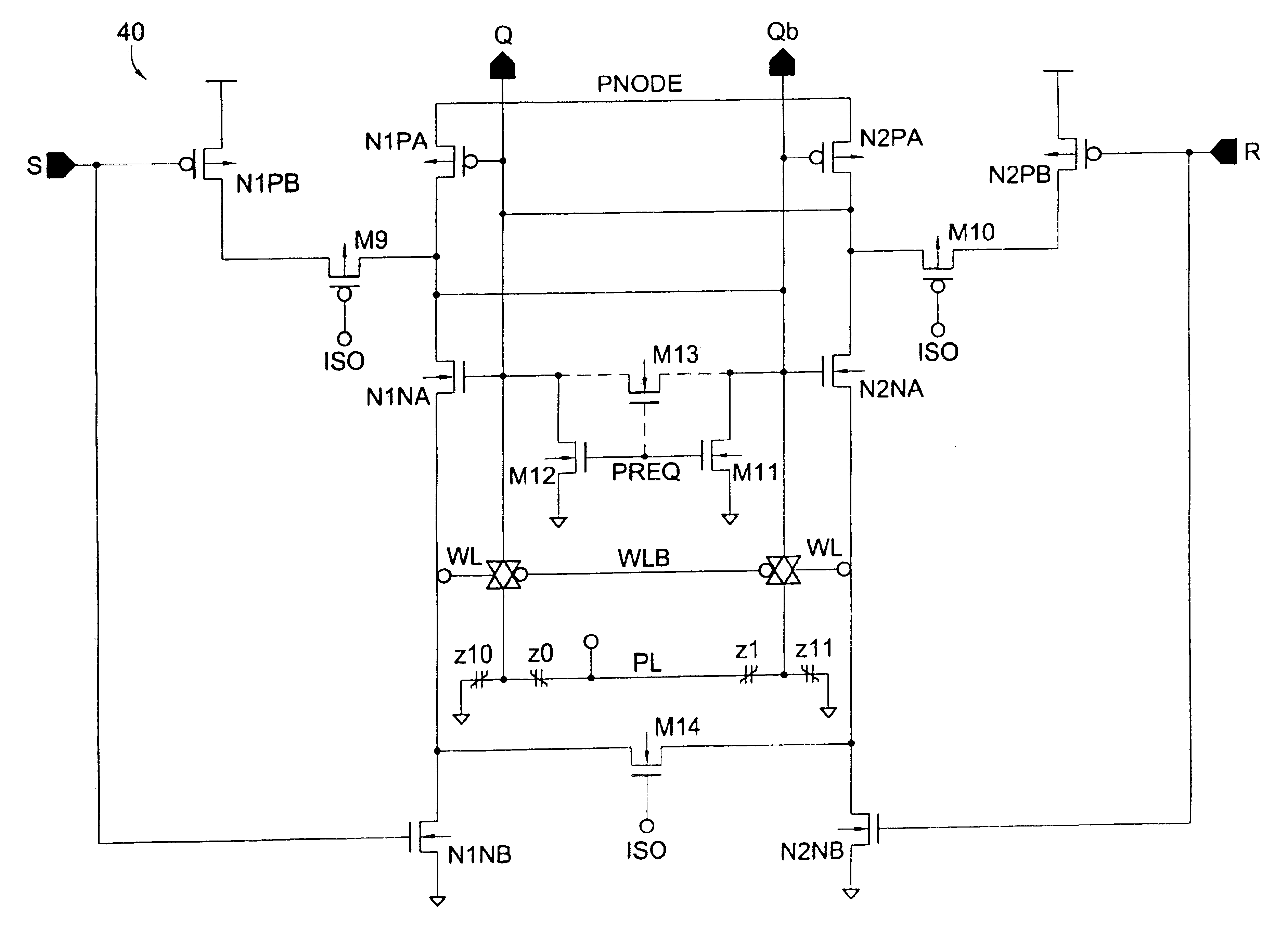
[0086]FIG. 2 is drawn so that the cross-coupled sense amplifier devices required for the ferroelectric non-volatile memory become apparent according to the present inve...


PUM


Abstract

Various logic elements such as SR flip-flops, JK flip-flops, D-type flip-flops, master-slave flip-flops, parallel and serial shift registers, and the like are converted into non-volatile logic elements capable of retaining a current output logic state even though external power is removed or interrupted through the strategic addition of ferroelectric capacitors and supporting circuitry. In each case, the building blocks of a cross-coupled sense amplifier are identified within the logic element and the basic cell is modified and/or optimized for sensing performance.

Description

CROSS-REFERENCE TO RELATED APPLICATIONS[0001]The present application is a divisional of U.S. patent application Ser. No. 10 / 076,058, filed Feb. 12, 2002, now U.S. Pat. No. 6,650,158, which claims priority to U.S. Provisional Application No. 60 / 273,870, filed Mar. 7, 2001 and U.S. Provisional Application No. 60 / 270,500, filed Feb. 21, 2001, the disclosures of all three applications being incorporated herein in their entirety by this reference.FIELD OF THE INVENTION[0002]This invention relates generally to logic elements such as SR flip-flops, JK flip-flops, D-type flip-flops, master-slave flip-flops, parallel and serial shift registers, and the like and, more particularly, to logic elements that are rendered non-volatile by the addition of ferroelectric capacitors and supporting circuitry.BACKGROUND OF THE INVENTION[0003]Integrated circuits can be divided into analog functions and digital functions. Most digital functions can be implemented using the following elements: combinatorial...

Claims


Application Information

Patent Timeline
Patent Type & Authority Patents(United States)
IPC IPC(8): G11C11/22G11C19/00H03K3/356H03K3/00H03K3/45G11C19/28H01L21/8238H01L21/8246H01L27/092H01L27/105H03K19/185
CPCG11C11/22H03K3/356008G11C19/005H03K3/45
Inventor ELIASON, JARROD
Owner MONTEREY RES LLC
Why Eureka
Try Eureka