Phase locked loop circuit with selectable variable frequency dividers

Inactive Publication Date: 2005-05-17
SANYO ELECTRIC CO LTD +1
View PDF6 Cites 11 Cited by
  • Summary
  • Abstract
  • Description
  • Claims
  • Application Information

AI Technical Summary

Benefits of technology

[0010]The present invention has been devised to overcome these conventionally encountered disadvantages, and it is an object of the present invention to prov

Problems solved by technology

Thus, this circuit performs phase comparison only once during one period of the reference signal, resulting in a first disadvantage of having a short lock-up time (i.e., the time required to synchronize with the output signal).
This second disadvantage has been found to stem from the provision of a plurality of frequency dividers.
If further reduction of the lock-up time is attempted by performing phase comparison 16 times during one period of the reference signal, it is necessary to use 16 frequency dividers, leading to higher electric power consumption.
Moreover, the use of a plurality of frequency dividers, which each occupy a considerably large space, makes the device as a whole large, expensive, and difficult to fabricate in the form of an LSI.
However, while these feedback signals are being output si

Method used


Image

  • Phase locked loop circuit with selectable variable frequency dividers
  • Phase locked loop circuit with selectable variable frequency dividers
  • Phase locked loop circuit with selectable variable frequency dividers

Examples


Embodiment Construction

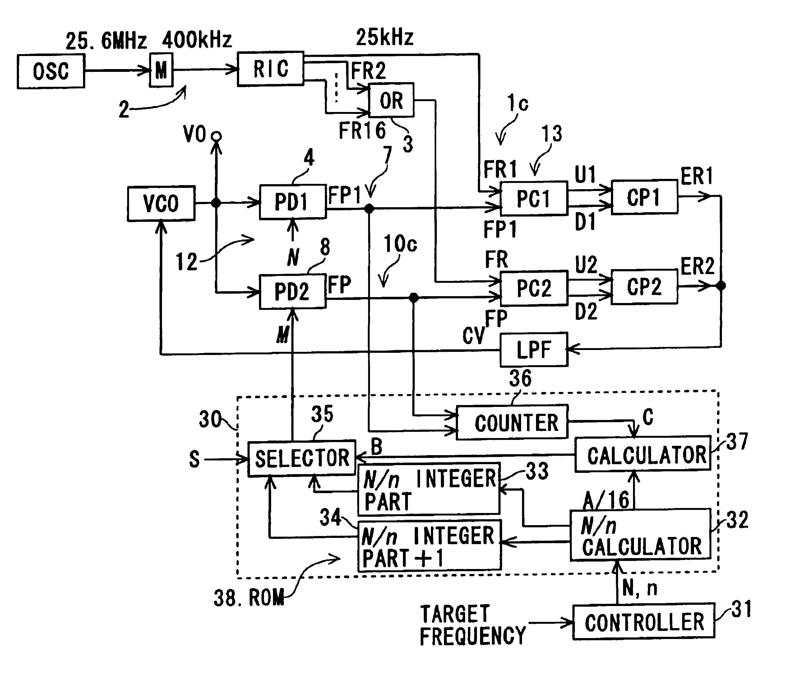
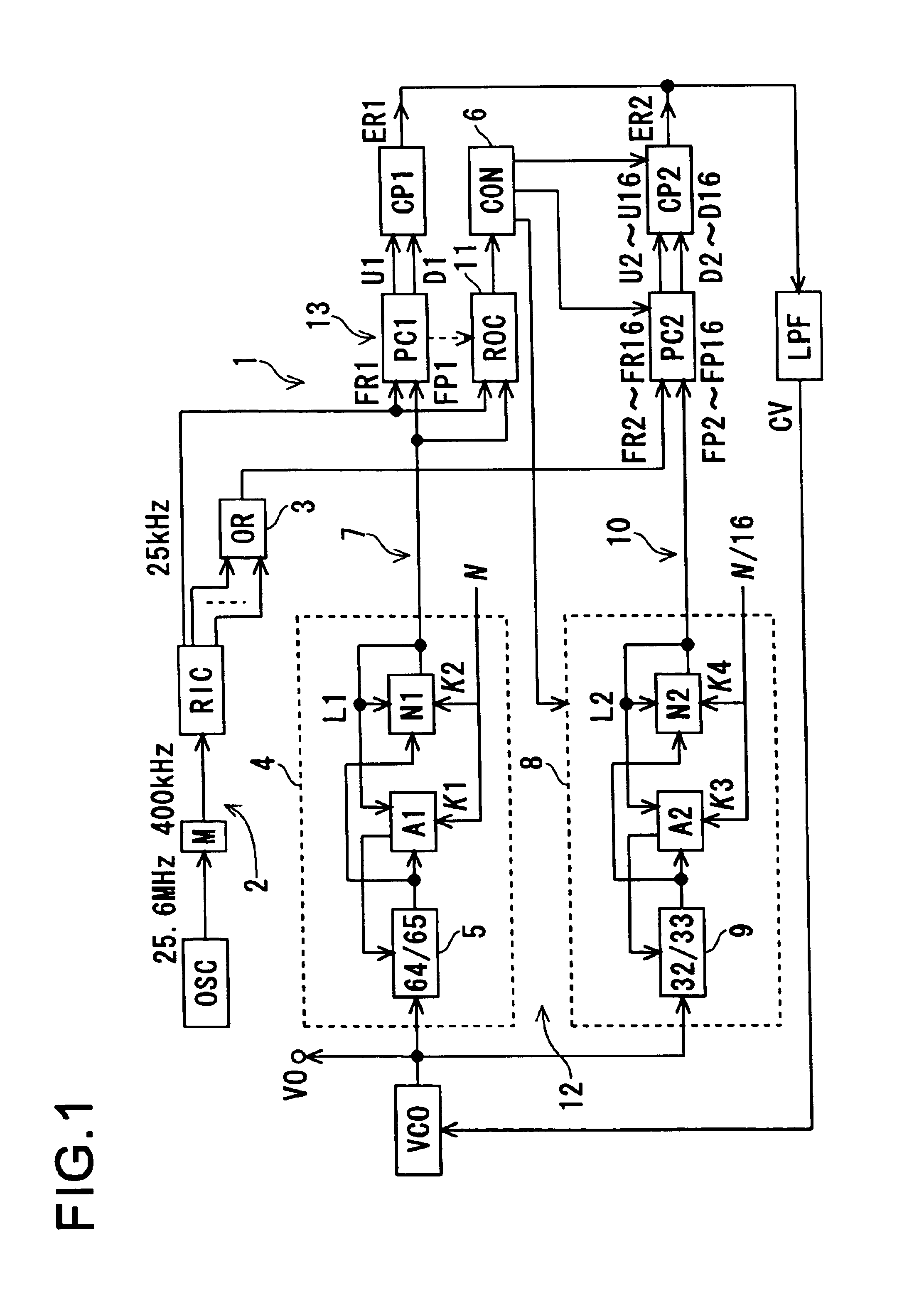
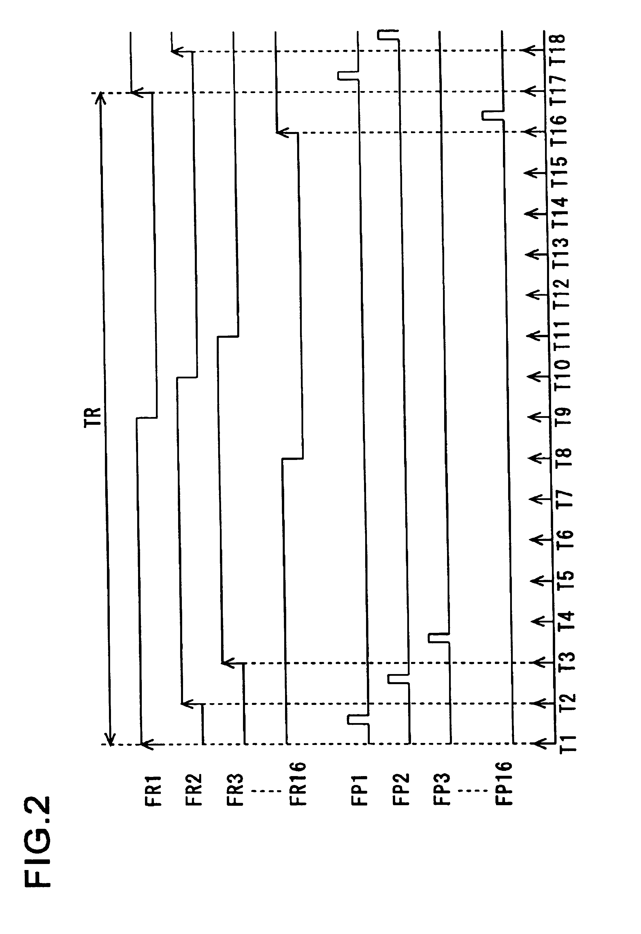
[0024]Hereinafter, with reference to FIGS. 1 and 2, the PLL circuit 1 of a first embodiment of the invention will be described. FIG. 1 is a block diagram of the PLL circuit 1, and FIG. 2 is a time chart of the relevant signals used in the PLL circuit 1.

[0025]In these figures, a reference signal generator 2 is composed of, for example, a reference oscillator OSC, a fixed frequency divider M, a ring counter RIC, an OR gate 3, and other components. The fixed frequency divider M performs frequency division by a division factor of, for example, 64, and is connected between the reference oscillator OSC and the ring counter RIC. The fixed frequency divider M divides by a division factor of 64 the signal output from the reference oscillator OSC (oscillating at a frequency of, for example, 25.6 Mhz), and feeds the resulting signal (having a frequency of 400 kHz) to the ring counter RIC.

[0026]The ring counter RIC is composed of, for example, 16 flip-flops (not shown) connected together, and o...


PUM


Abstract

A PLL circuit comprises a reference signal generating unit for generating reference signals of different phases, variable frequency dividers for dividing the frequency of the output signal of a voltage-controlled oscillator (VCO) and thereby outputting feedback signals, and a phase comparator for comparing the phase of each feedback signal with that of the corresponding reference signal and thereby outputting phase comparison signals. When the output signal is synchronized with a preset frequency signal, at least one variable frequency divider of the variable frequency dividers is operated, and the operation of the other is stopped.

Description

CROSS-REFERENCE TO RELATED APPLICATION[0001]This application is a National Stage entry of International Application No. PCT / JP02 / 00211, filed Jan. 15, 2002.TECHNICAL FIELD[0002]The present invention relates to a PLL circuit.BACKGROUND ART[0003]A conventional example of this kind of circuit is shown in “SANYO TECHNICAL REVIEW,” Vol. 10, No. 1, February, 1978, page 32. However, this circuit is of the single-phase-comparator type (that is, it uses only one stage of a phase comparator). Thus, this circuit performs phase comparison only once during one period of the reference signal, resulting in a first disadvantage of having a short lock-up time (i.e., the time required to synchronize with the output signal).[0004]A proposal to overcome this disadvantage is made in the Japanese Patent Application Laid-Open No. H10-135822. According to this publication, there are provided a reference signal generator that produces a plurality of reference signals having different phases from each other,...

Claims


Application Information

Patent Timeline
IPC IPC(8): H03L7/087H03L7/08H03L7/191H03L7/193H03L7/16H03L7/089H03L7/095H03L7/197
CPCH03L7/0802H03L7/087H03L7/191H03L7/193H03L7/0891H03L2207/18H03L7/1974H03L7/095
Inventor SUMI, YASUAKIMORIMOTO, NORIO
Owner SANYO ELECTRIC CO LTD
Why Eureka
Try Eureka