Temperature compensation mechanism for a micromechanical ring resonator

a temperature compensation mechanism and micromechanical technology, applied in the field of time base, can solve the problems of increasing the mass moment of inertia of the structure, reducing the resonant frequency,

Inactive Publication Date: 2005-05-17
ETA SA MFG HORLOGERE SUISSE
View PDF9 Cites 23 Cited by
  • Summary
  • Abstract
  • Description
  • Claims
  • Application Information

AI Technical Summary

Benefits of technology

[0020]An object of the present invention is to provide a mechanism for substantially compensating for the effect of temperature on the resonant frequency of the ring resonator which does not require an additional temperature measuring circuit or an additional resonator.

Problems solved by technology

Secondly, due to thermal expansion, the diameter of the ring will increase with increasing temperature resulting in an increased mass moment of inertia of the structure, which, in turn, also reduces the resonant frequency.

Method used


Image

  • Temperature compensation mechanism for a micromechanical ring resonator
  • Temperature compensation mechanism for a micromechanical ring resonator
  • Temperature compensation mechanism for a micromechanical ring resonator

Examples


Embodiment Construction

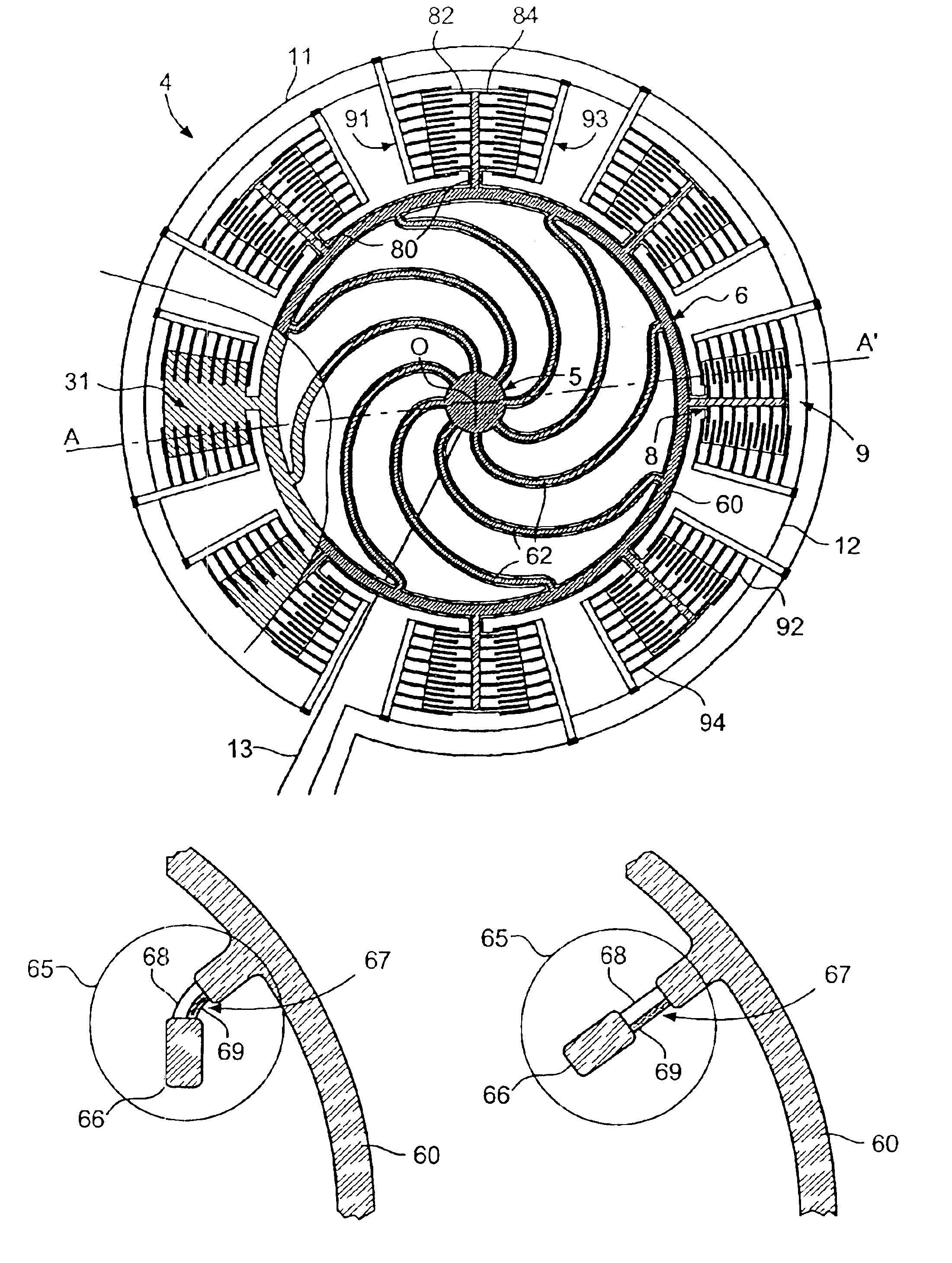
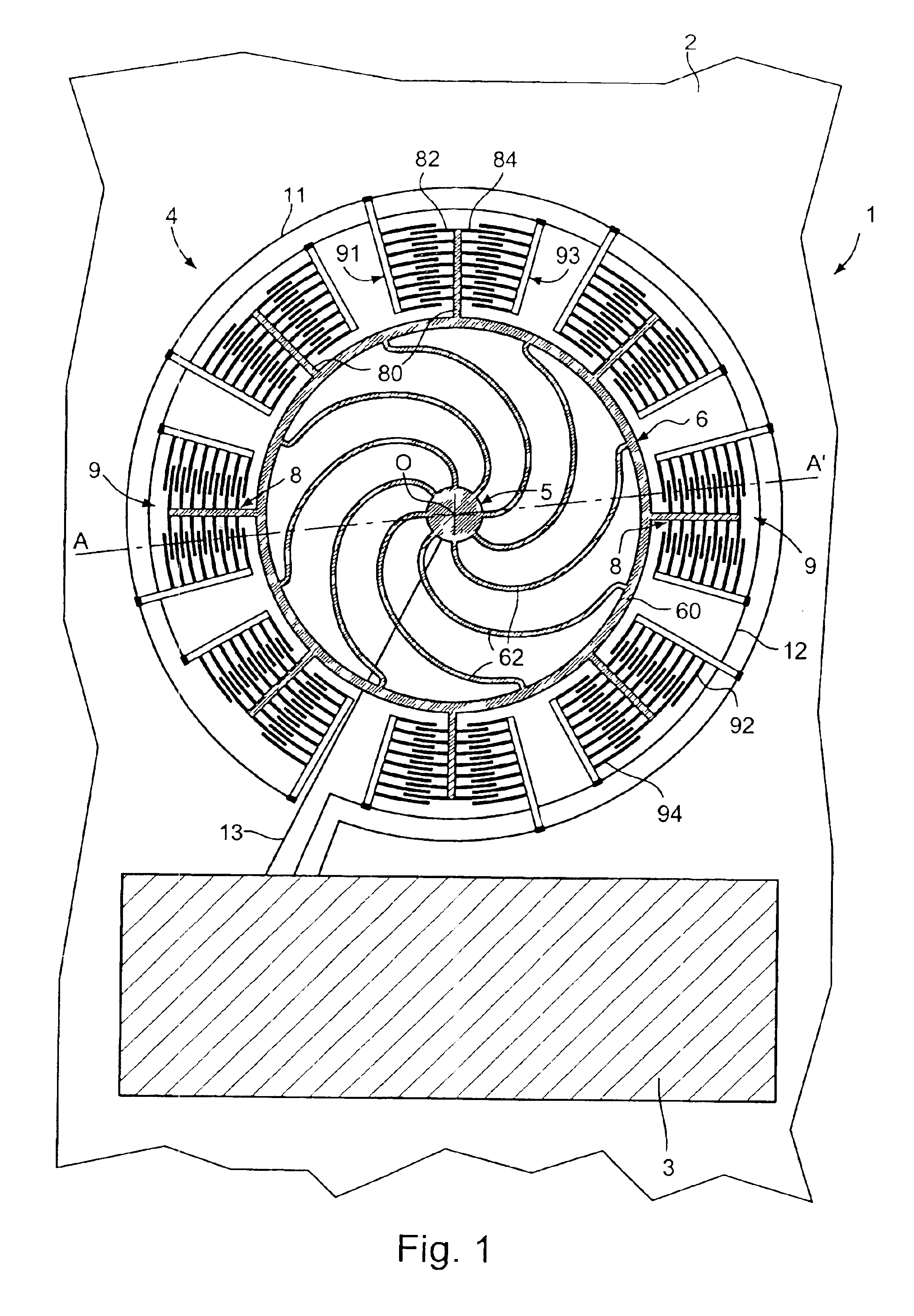
[0035]FIG. 1 schematically shows a top view of a first embodiment of a time base. There is shown an integrated time base, indicated generally by reference numeral 1, comprising a resonator 4 and an integrated electronic circuit 3 for driving the resonator into oscillation and for producing, in response to this oscillation, a signal having a determined frequency. FIG. 4 shows a cross-sectional view of the ring resonator 4 taken along line A-A′ as shown in FIG. 1.

[0036]The integrated electronic circuit 3 is not shown in detail since this circuit may easily be designed by those skilled in the art. Preferably both the integrated electronic circuit 3 and the resonator 4 are realized and integrated on a same substrate 2 as illustrated in FIG. 1. A preferred substrate material is silicon, but other similar materials known by those skilled in the art to be equally suitable for realising the time base of the present invention may be used.

[0037]The resonator 4 is realised in the form of a mon...


PUM


Abstract

A time base including a resonator (4) and an integrated electronic circuit (3) for driving the resonator into oscillation and for producing, in response to the oscillation, a signal having a determined frequency. The resonator is an integrated micromechanical ring resonator supported above a substrate (2) and adapted to oscillate around an axis of rotation (O) substantially perpendicular to the substrate. The ring resonator includes a free-standing oscillating structure having a plurality of thermally compensating members (65) which are adapted to alter a mass moment of inertia of the free-standing oscillating structure as a function of temperature so as to compensate for the effect of temperature on the resonant frequency of the ring resonator.

Description

RELATED APPLICATION[0001]This application is a division of U.S. patent application Ser. No. 10 / 129,193 (now U.S. Pat. No. 6,686,807) filed on May 2, 2002 in the name of Metin GIOUSOUF et al. and entitled “Time base comprising an integrated micromechanical ring resonator” which is assigned to the present Assignee, and which is incorporated herein by reference.TECHNICAL FIELD[0002]The present invention relates to a time base, i.e. a device comprising a resonator and an integrated electronic circuit for driving the resonator into oscillation and for producing, in response to this oscillation, a signal having a determined frequency as well as to a resonator for use in such a time base. The present invention more particularly relates to a compensation mechanism for compensating for the effect of temperature on the resonant frequency of the resonator.BACKGROUND ART[0003]Time bases, or frequency standards, are required in a large variety of electronic devices, ranging from wristwatches and...

Claims


Application Information

Patent Timeline
Patent Type & Authority Patents(United States)
IPC IPC(8): G01C19/56H03B5/30B81B3/00G04G3/00G01C19/5684G01C19/5712G04F5/04H03B5/32H03H9/24
CPCH03B5/30G01C19/5712
Inventor GIOUSOUF, METINKUCK, HEINZPLATZ, RAINER
Owner ETA SA MFG HORLOGERE SUISSE
Why Eureka
Try Eureka