Method to balance mass moments of a drive unit and drive unit for performance of such a method

a technology of mass moments and drive units, which is applied in the direction of crankshafts, inertia force compensation, machines/engines, etc., can solve the problems of fatigue rupture, high rotary vibration amplitude, and negative affecting driving comfor

Inactive Publication Date: 2013-07-04
FORD GLOBAL TECH LLC
View PDF1 Cites 6 Cited by
  • Summary
  • Abstract
  • Description
  • Claims
  • Application Information

AI Technical Summary

Benefits of technology

[0003]The disclosure concerns a method to balance the mass moments provoked by the mass forces of the 1st order of a crank drive of an internal combustion engine. The crank drive belongs to a drive unit with at least one cylinder, wherein the crank drive comprises a crankshaft and at least one piston pivoted on this crankshaft. The piston ...

Problems solved by technology

These rotary vibrations lead to noises both from body-borne sound emission and from body-borne sound introduced into the bodywork and into the internal combustion engine, wherein vibrations can also occur which negatively affect driving comfort, for example, vibrations of the steering wheel in the passenger compartment.
When the crankshaft is excited in its inherent frequency range, high rotary vibration amplitudes can occur which can even lead to fatigue rupture.
The rotary vibrations of the crankshaft are transmitted undesirably to the camshaft via the timing gears or camshaft drive, wherein the camshaft itself also constitutes a vibratable system and can excite other systems, in particular the valve drive, to vibrate.
A full mass balance cannot always be achieved, so further measures must be taken.
Th...

Method used


Image

  • Method to balance mass moments of a drive unit and drive unit for performance of such a method
  • Method to balance mass moments of a drive unit and drive unit for performance of such a method
  • Method to balance mass moments of a drive unit and drive unit for performance of such a method

Examples


third embodiment

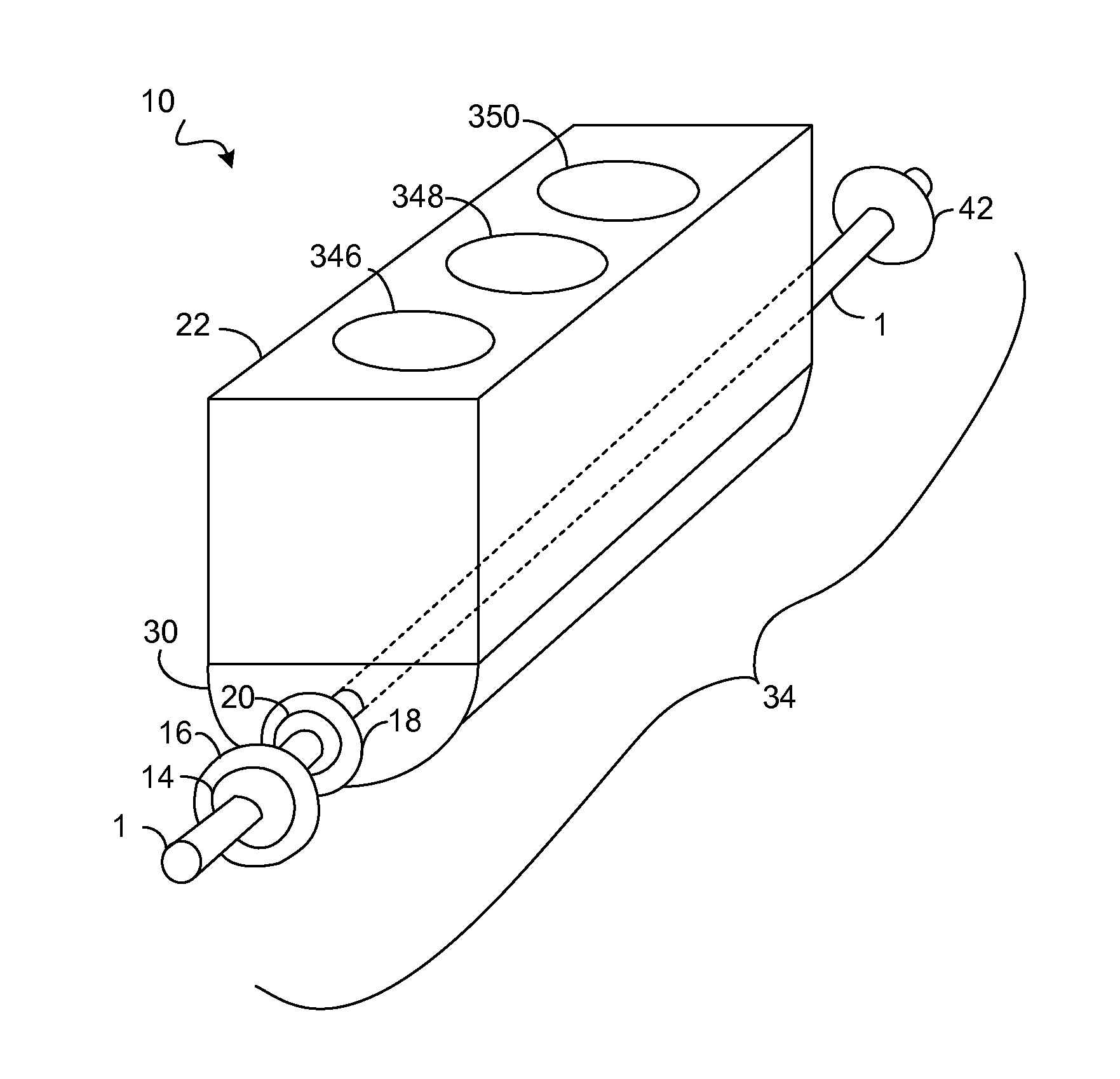
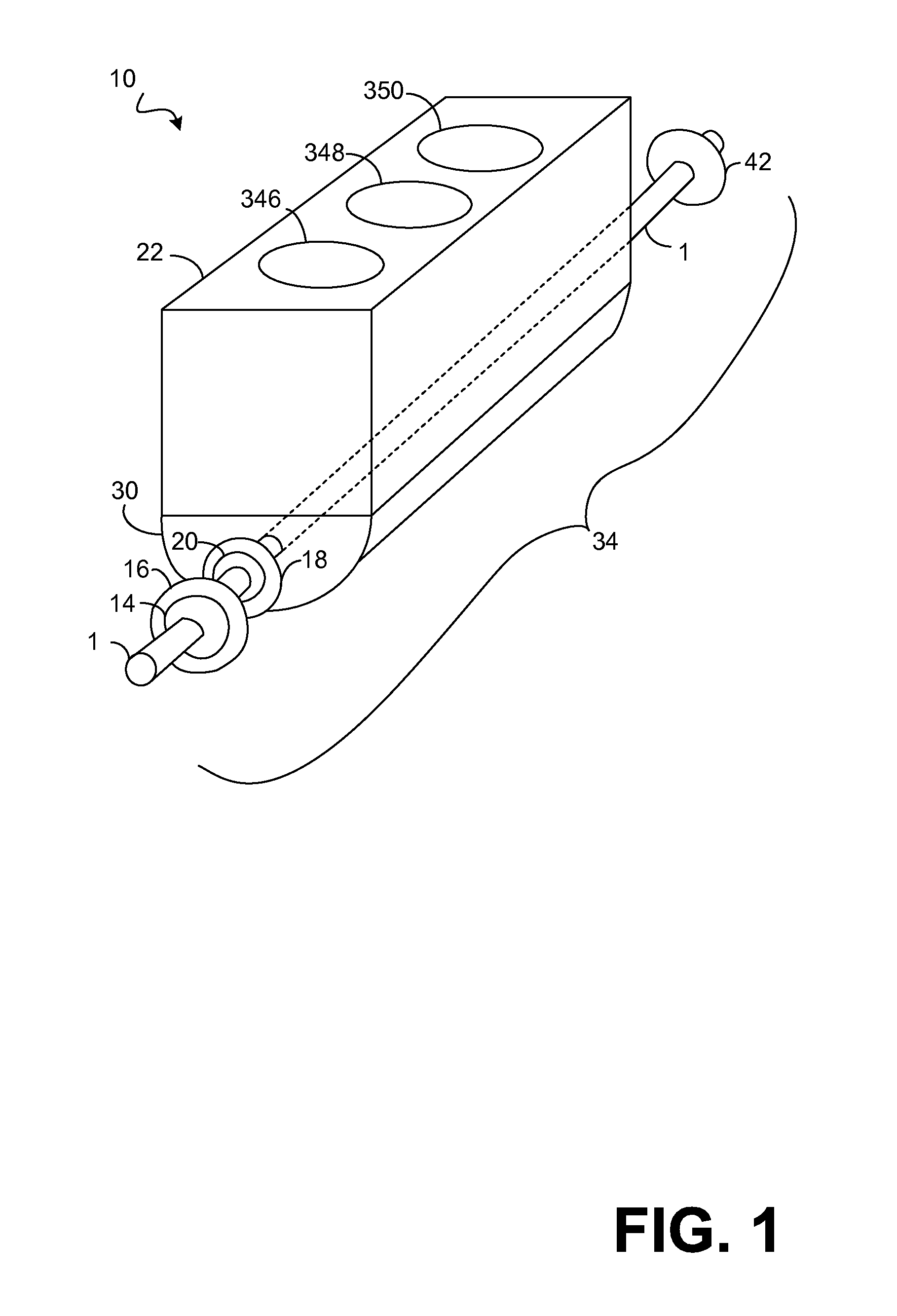
[0047]In this example crank drive 34 contains a flywheel 42, gear wheel 16 and second gear wheel 14, and traction mechanism drive 18 with a wheel 20 outside the traction mechanism drive 18. The traction mechanism drives a wheel arranged on the outside of the traction mechanism. In one embodiment the second balance weight is provided on this wheel rotating in the opposite direction to the crankshaft. In another embodiment, a gear wheel which is arranged on the crankshaft and is in engagement with a second gear wheel, wherein the second balance weight is provided on the second gear wheel and rotates in the opposite direction to the crankshaft. In a third embodiment, a flywheel is arranged on the crankshaft, wherein the first balance weight is provided on the flywheel.

[0048]Several examples of existing components of the drive unit on which the balancing weights may be arranged are provided. However, these examples need not be limiting and there may be additional elements on a crank dri...

first embodiment

[0051]FIG. 3 shows the crankshaft 1 of the drive unit in a perspective view. This is the crankshaft 1 of a three-cylinder in-line engine which comprises three cylinder crank assemblies 2a, 2b, and 2c arranged in line along the longitudinal axis 1b of the crankshaft 1. The crankshaft pins 3a, 3b, and 3c of the three cylinder crank assemblies 2a, 2b, and 2c are formed offset to each other by 120° about the longitudinal axis 1b so that the rotating mass forces of the 1st order and 2nd order of the oscillating substitute masses are balanced with corresponding ignition timing.

[0052]The mass forces of the rotating substitute masses are balanced in their external effect by the counterweights 4a, 4b, and 4c arranged on the crankshaft 1. Here, in the region of each crankshaft pin 3a, 3b, and 3c are arranged two counterweights 4a, 4b, and 4c, namely on the side of the crankshaft 1 opposite the crankshaft pin 3a, 3b, and 3c.

[0053]To balance the mass moments provoked by the mass forces of the ...


PUM


Abstract

A method to balance a crank drive of an internal combustion engine comprising: using a balancer unit comprising a first balance weight and a second balance weight serving as counterbalance; rotating the first and second balance weight at an engine rotation speed when a crankshaft rotates at the engine rotation speed; rotating the first balance weight in a same direction as the crankshaft; rotating the second balance weight in an opposite direction to the crankshaft; arranging the first balance weight and the second balance weight such that a resulting balancing moment about a velocity pole of a 1st order of a rigid body rotation of a drive unit at least partially balances a rotary movement about a velocity pole provoked by a resulting mass moment of the 1st order, an external effect of the resulting mass moment of the 1st order being at least partially balanced.

Description

CROSS REFERENCE TO RELATED APPLICATIONS[0001]The present application claims priority to German Application 102012200028.3, filed on Jan. 3, 2012, the entire contents of which are hereby incorporated by reference for all purposes.TECHNICAL FIELD[0002]The disclosure relates to a crank drive of an internal combustion engine and a method to balance mass moments thereof.BACKGROUND AND SUMMARY[0003]The disclosure concerns a method to balance the mass moments provoked by the mass forces of the 1st order of a crank drive of an internal combustion engine. The crank drive belongs to a drive unit with at least one cylinder, wherein the crank drive comprises a crankshaft and at least one piston pivoted on this crankshaft. The piston belongs to the at least one cylinder. The crank drive of the present disclosure uses a balancer unit comprising two balance weights which rotate with the engine rotation speed when the crankshaft rotates with engine rotation speed. The effect of the resulting mass m...

Claims


Application Information

Patent Timeline
IPC IPC(8): F02B75/06
CPCF16F15/26F02B75/065F16C3/06
Inventor ROEHRIG, MICHAEL
Owner FORD GLOBAL TECH LLC
Why Eureka
Try Eureka