
Electrical power control and sensor module for a wireless system

Inactive Publication Date: 2005-05-17
ROYAL THOUGHTS
View PDF168 Cites 118 Cited by
  • Summary
  • Abstract
  • Description
  • Claims
  • Application Information

AI Technical Summary

Benefits of technology

[0015]Various embodiments include additional elements that provide enhanced functionality. For example, the wall mounted module may include a photosensor that generates a signal based on ambient light conditions. The signal may be used to control the operation of the module. As another example, the wall mounted module may include an audio transducer. The transducer may be part of an intercom system or it may include a siren that audibly signals an alarm condition. As another example, the wall mounted module may included a battery power supply. The battery power supply is sufficient to power the transceiver (or other communication module), an internal processor and the motion detector.

Problems solved by technology

Among the recognized problems of security system are the high monetary costs of the system.
The fixed costs of the many sensors, the keypad, the control panel, and wiring discourage many from investing.
Professional system design, installation and continuous monitoring are additional costs.
Furthermore, many people find that, with time, the task of arming and disarming the system becomes an excessively routine burden with no tangible benefit.
The occasional false alarm, and any penalty fees assessed by the monitoring service or emergency service, further dissuade diligent use of a security system.
Eventually, the system falls into disuse and the homeowner regrets having made the investment.
With few exceptions, wireless remote control of home appliances has not yet received broad public acceptance.
Television and video cassette recorder (VCR) remote controls, and garage door openers often use proprietary signaling protocol and are thus, limited in functionality.
For example, a remote control for use with a particular television is incapable of controlling a garage door opener.
Furthermore, the range of such devices is limited.
Also, most such remote controls do not provide feedback to the user to indicate changes or settings in the controlled device.
Thus, it appears that the range of most remote controls is, as a practical matter, limited by the user's ability to see the changes made.

Method used


Image

  • Electrical power control and sensor module for a wireless system
  • Electrical power control and sensor module for a wireless system
  • Electrical power control and sensor module for a wireless system

Examples


Embodiment Construction

[0025]In the following detailed description of the preferred embodiments, reference is made to the accompanying drawings which form a part hereof, and in which is shown by way of illustration specific illustrative embodiments in which the invention may be practiced. These embodiments are described in sufficient detail to enable those skilled in the art to practice the invention, and it is to be understood that other embodiments may be utilized and that logical, mechanical and electrical changes may be made without departing from the spirit and scope of the present invention. The following detailed description is, therefore, not to be taken in a limiting sense.

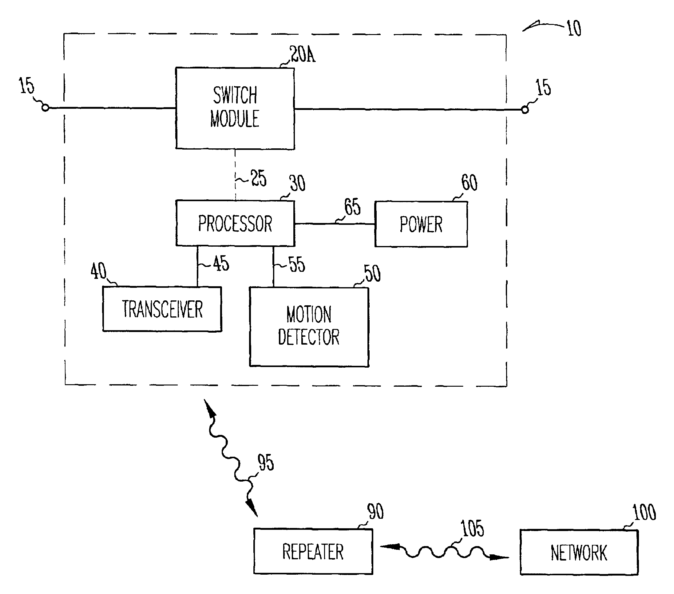
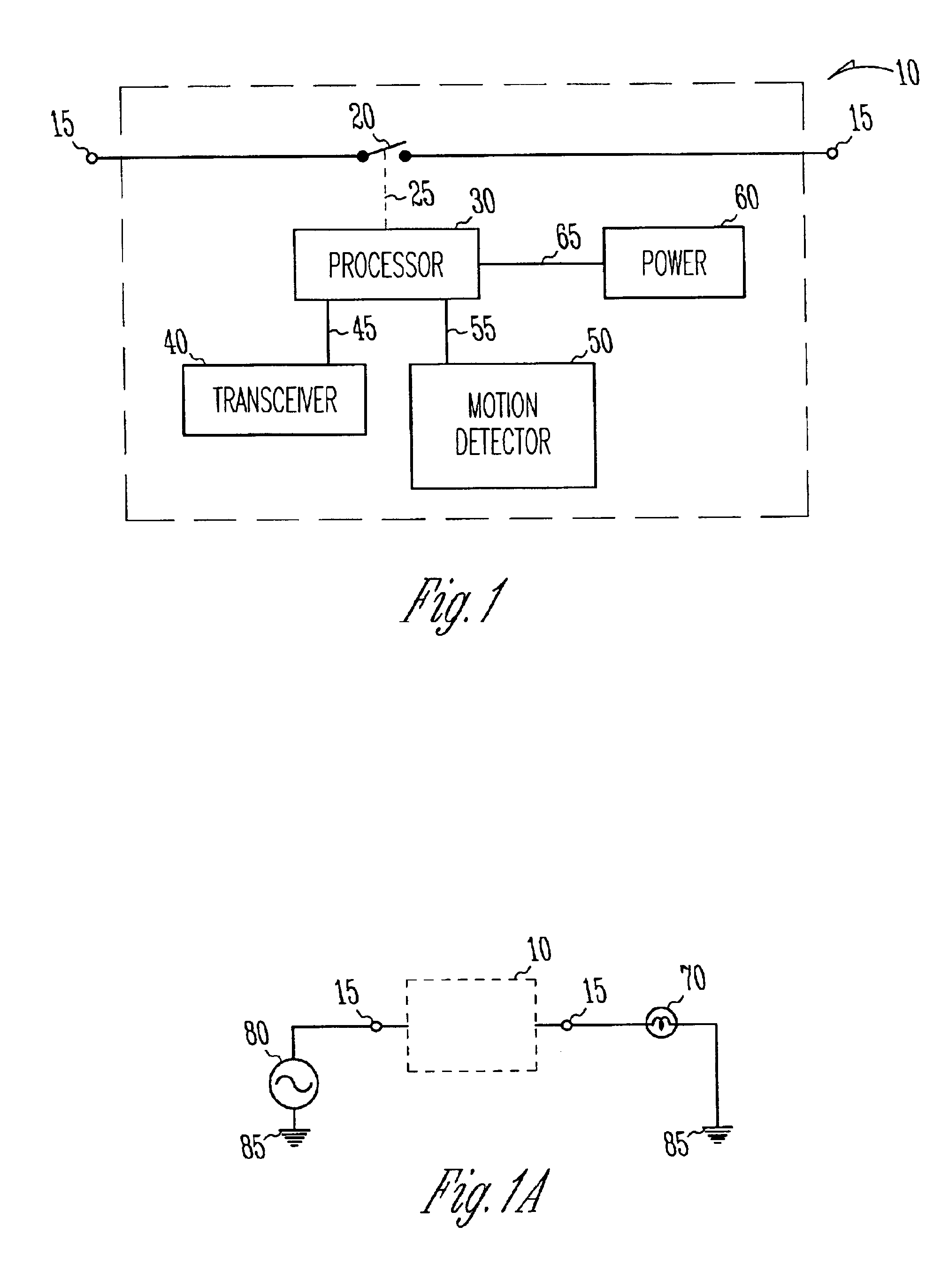
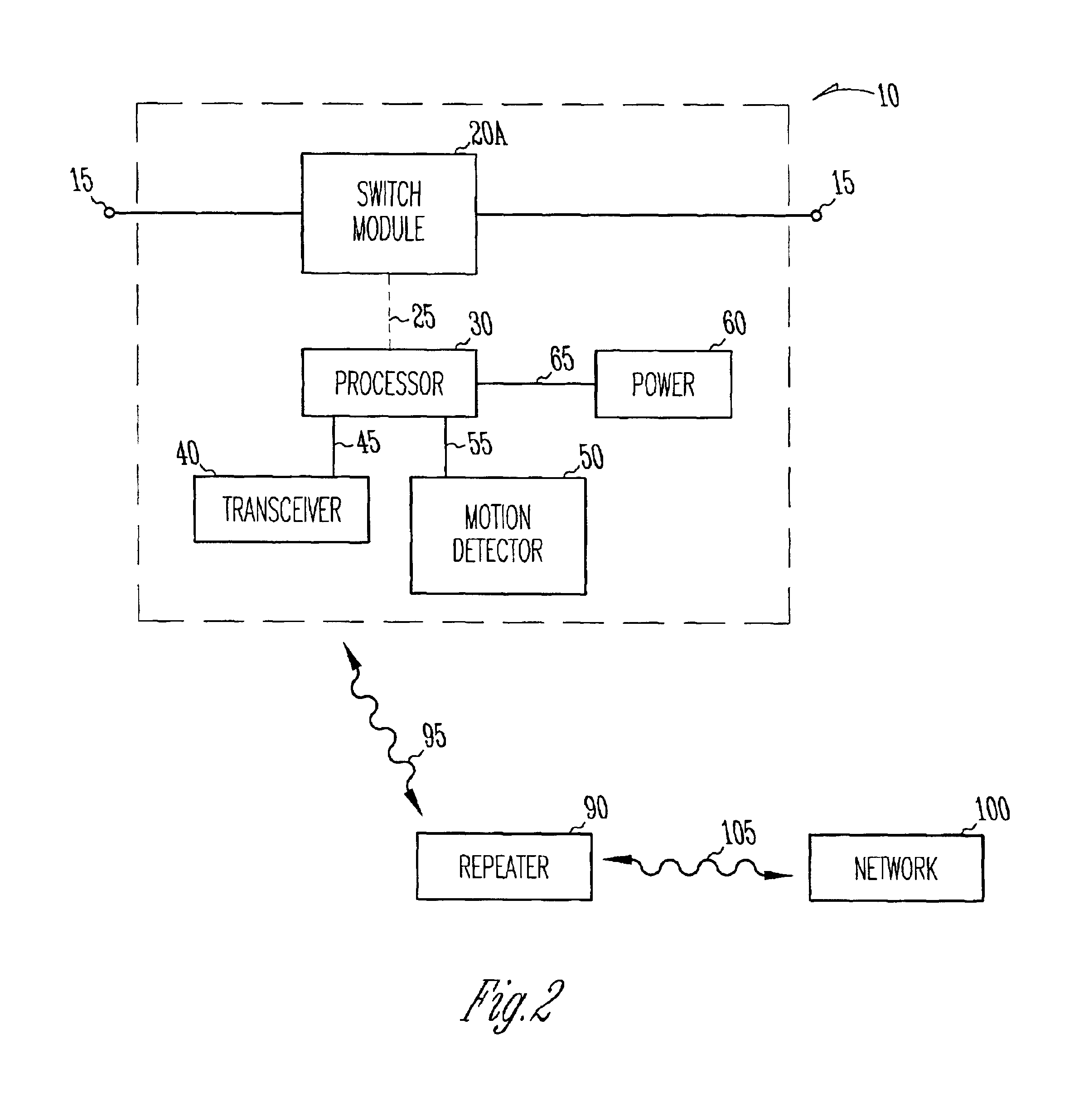
[0026]FIG. 1 schematically illustrates a block diagram of one embodiment of module 10. Module 10, illustrated by the dashed box, includes switch 20, processor 30, power supply 60, transceiver 40 and motion detector 50. Switch 20 is coupled to processor 30 by dashed line 25 to indicate that positional information relative to swi...


PUM


Abstract

A module having a switch, a processor, a motion detector and a wireless transceiver. The module controls the operation of an electrical load, such as a light, based on the switch position, programming executing on the processor, an output from the motion detector or an output signal from the transceiver. The module transmits information corresponding to the electrical load, switch position, programming and detected motion. In one embodiment, the module is battery powered. In various embodiments, the module includes an intercom, a high intensity siren, and a photosensor having an output as a function of an ambient light level. In one embodiment, the module is compatible with a wireless communication protocol such as is used with BLUETOOTH®.

Description

TECHNICAL FIELD OF THE INVENTION[0001]The present invention relates generally to the field of wireless control and monitoring and, in particular, to a system for controlling and monitoring electrical power to a load.BACKGROUND OF THE INVENTION[0002]A concern for personal safety has compelled many people to install a home security system. A typical security system includes a number of sensors distributed throughout the house and a security alarm panel. A keypad, often positioned near an entry door and connected to the alarm panel, allows the owner to arm or disarm the system. The sensors are configured to detect intruders or other hazardous conditions, such as fire or smoke. The security alarm panel is often connected to a telephone line and is programmed to contact a remote facility if the sensors detect an alarm condition. The remote facility is staffed by operators who contact a local dispatch service to respond to the alarm condition.[0003]For many people, the advantage of protec...

Claims


Application Information

Patent Timeline
IPC IPC(8): G08B13/22G08B25/10
CPCG08B25/008G08B25/10G08B25/009
Inventor MENARD, RAYMOND J.QUADY, CURTIS E.
Owner ROYAL THOUGHTS
Learn More