Automatic implementation of network configuration changes

a network configuration and automatic implementation technology, applied in the field of communication networks, can solve the problems of dslam and the cpe to dedicate an excessive amount of computing power to interface management, and cannot guarantee reliable delivery

Inactive Publication Date: 2005-05-17
ORCKIT CORP
View PDF18 Cites 55 Cited by
  • Summary
  • Abstract
  • Description
  • Claims
  • Application Information

AI Technical Summary

Benefits of technology

[0024]There is additionally provided, in accordance with a preferred embodiment of the present invention, client premises equipment (CPE), which is adapted to receive a trap message from a network end switch over a network connection therebetween, informing the CPE of a change in a network management information base (MIB) of the end switch, and responsive to the trap message, to read information from the MIB without polling the end switch for further trap messages.

Problems solved by technology

Trap packets are sent using the User Datagram Protocol (UDP), which generally provides fast service but does not guarantee reliable delivery.
Adherence to the conventional ILMI model under these conditions would require both the DSLAM and the CPE to dedicate an excessive amount of computing power to interface management.

Method used


Image

  • Automatic implementation of network configuration changes
  • Automatic implementation of network configuration changes
  • Automatic implementation of network configuration changes

Examples


Embodiment Construction

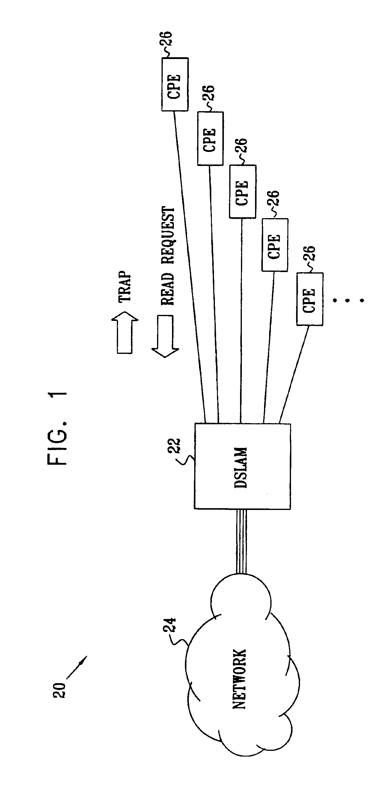
[0029]FIG. 1 is a block diagram that schematically illustrates a network access multiplexing system 20, in accordance with a preferred embodiment of the present invention. A DSLAM 22 comprises multiple interface connections, providing access to a network 24 for a plurality of subscribers having respective client premises equipment (CPE) 26. Network 24 preferably comprises an ATM network, and CPE 26 is configured to provide ATM service directly to the subscriber premises.

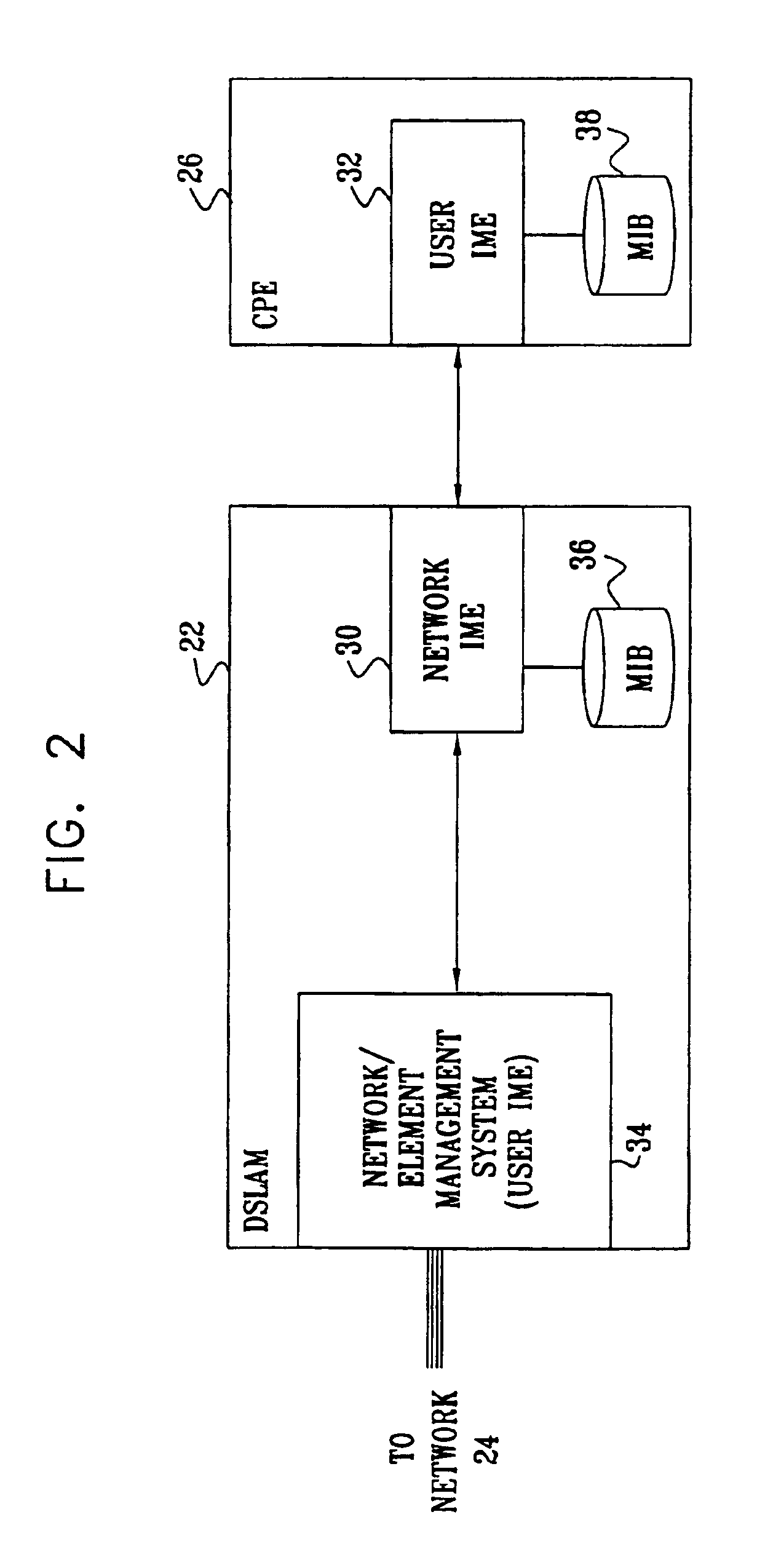
[0030]FIG. 2 is a block diagram that schematically shows interface management features of DSLAM 22 and of one of CPEs 26, in accordance with a preferred embodiment of the present invention. In accordance with the ILMI model, the connection between DSLAM 22 and CPE 26 is managed by a pair of IMEs: a network-side IME 30 maintained by the DSLAM, and a user-side IME 32 maintained by the CPE. The IMEs typically comprise central processing units (CPUs) running suitable network management software (frequently in addition to...


PUM


Abstract

A method for network management includes sending a trap message from a network end switch to client premises equipment (CPE) over a network connection therebetween, informing the CPE of a change in a network management information base (MIB) of the end switch. A request from the CPE to the end switch, subsequent to the trap message, to read information from the MIB, and the information is provided from the end switch to the CPE responsive to the request. The change is determined to have been implemented by the CPE based on the request to read the information. There is thus no need for the CPE to poll the processor for further trap messages.

Description

FIELD OF THE INVENTION[0001]The present invention relates generally to communication networks, and specifically to automated management of network connections.BACKGROUND OF THE INVENTION[0002]In modern networks, such as Asynchronous Transfer Mode (ATM) networks, the elements of the network use a management information base (MIB) to maintain common status and configuration information. The ATM MIB, for example, holds information concerning virtual path connections (VPCs), virtual channel connections (VCCs), registered services, registered ATM network prefixes and addresses, and capabilities available at ATM interfaces. All of the ATM devices in the network, such as switches and end-systems, use the MIB to determine how to conduct their network communications.[0003]In order to set up and maintain the MIB, the different ATM devices must exchange management information regarding status and configuration conditions. A variety of different methods and protocols for this information exchan...

Claims


Application Information

Patent Timeline
Patent Type & Authority Patents(United States)
IPC IPC(8): H04L12/28H04L12/24
CPCH04L12/2856H04L41/0816H04L12/2883
Inventor LEDERMAN, YARONVOLPERT, GALIT
Owner ORCKIT CORP
Why Eureka
Try Eureka