
Separation circuit for an echo canceling system and method of operating the same

a separation circuit and echo canceling technology, applied in the field of digital signal processing, can solve the problems of wasting bandwidth, affecting the quality of signal transmission, and affecting the transmission quality of bit pumps, and achieve the effect of enhancing the attenuation of the echo

Inactive Publication Date: 2005-05-17
LUCENT TECH INC
View PDF29 Cites 19 Cited by
  • Summary
  • Abstract
  • Description
  • Claims
  • Application Information

AI Technical Summary

Benefits of technology

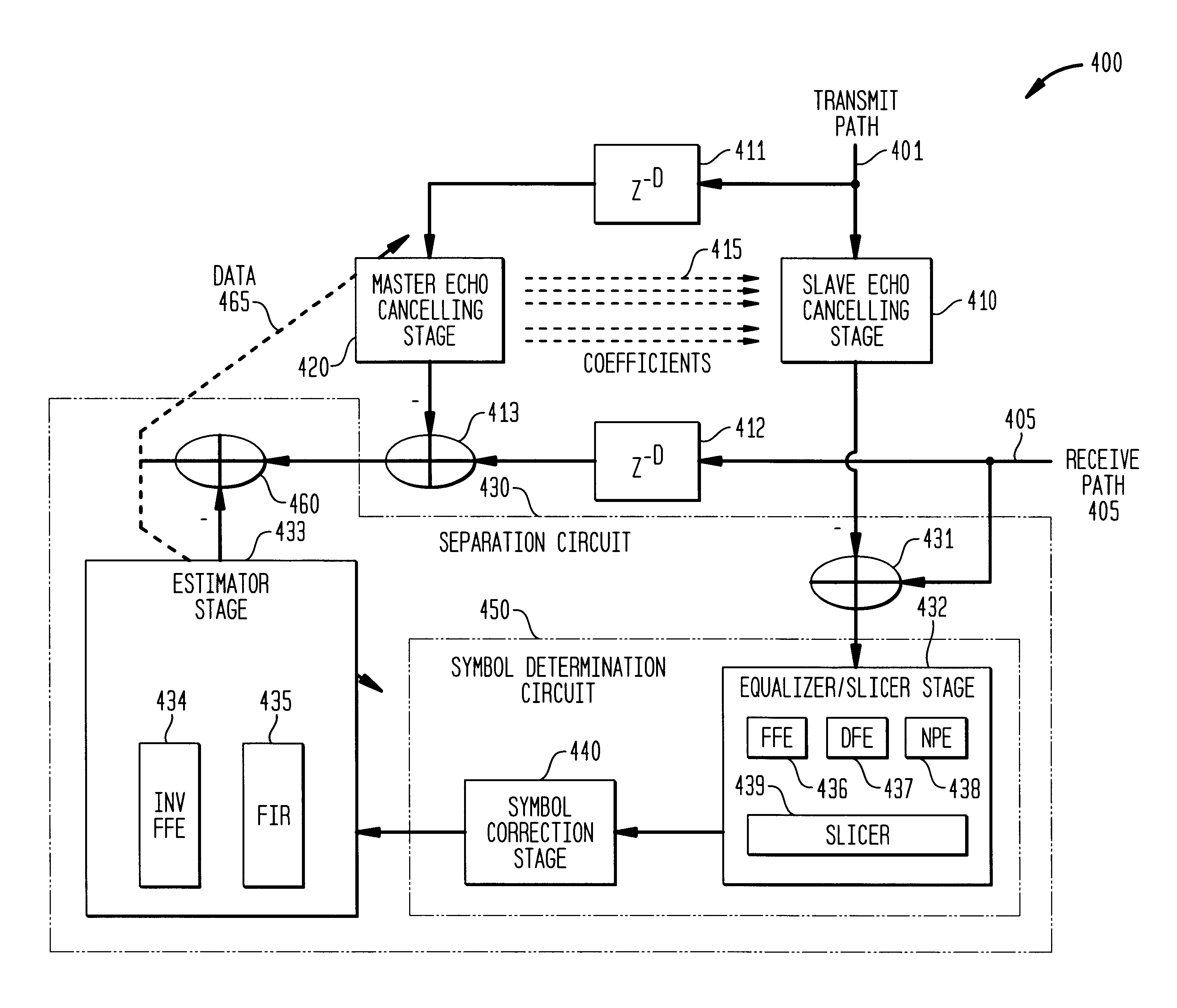
"The present invention introduces a separation circuit that can cancel out echoes in a network communication system. The circuit includes a symbol determination circuit and an estimator stage that generates data representing a residual level of the echo. The circuit can adaptively generate filter coefficients to attenuate the echo and improve the fidelity of the communication traffic. The invention reduces the echo to levels not previously attainable, thereby increasing the fidelity of communication traffic and reducing error back propagation probability associated therewith. The invention also includes an echo canceling system that employs master and slave echo canceling stages to attenuate the echo."

Problems solved by technology

Unfortunately, signal quality suffered greatly as distances increased.
Filters and amplifiers improved quality, but only to a limited extent.
Thus, it was decided that higher frequencies were of limited value and represented a waste of bandwidth if the traffic were to be digitized and transmitted.
Unfortunately, even in view of the most clever modems, the 4 kHz digitization cutoff has imposed an apparent limit on the speed of such devices.
Unfortunately, the analog local loops have unjustly taken most of the blame for the speed limitation.
Third, DSL-based technology requires relatively little equipment to combine and later separate speech and data streams.
Some technical challenges, however, remain for HDSL2.
An echo may easily be 15 decibels (dB) greater than a strong receive signal thereby making processing of the receive signal at least more difficult.
As the receive signal becomes weaker, acceptable processing of the receive signal becomes even more difficult due to the overriding effects of the echo.
This task is often made more difficult due to high levels of disturber signals, which are signal sources of crosstalk noise.
This approach has a fundamental problem with the speed and adaptability of the updates.
The reduction of the echo canceller update gain, however, results in an improper response for higher update values thereby lowering the ability of the echo canceller to track the necessary changes.
Therefore, the combination of lower update gains and higher disturber levels results in an echo being canceled with less precision thereby lowering the overall performance of the transceiver.
Present sensitivity to disturber signals can easily result in ten percent of the receive signals being erroneously estimated.
This action contributes to an additional degradation in the performance of the echo canceller.

Method used


Image

  • Separation circuit for an echo canceling system and method of operating the same
  • Separation circuit for an echo canceling system and method of operating the same
  • Separation circuit for an echo canceling system and method of operating the same

Examples


Embodiment Construction

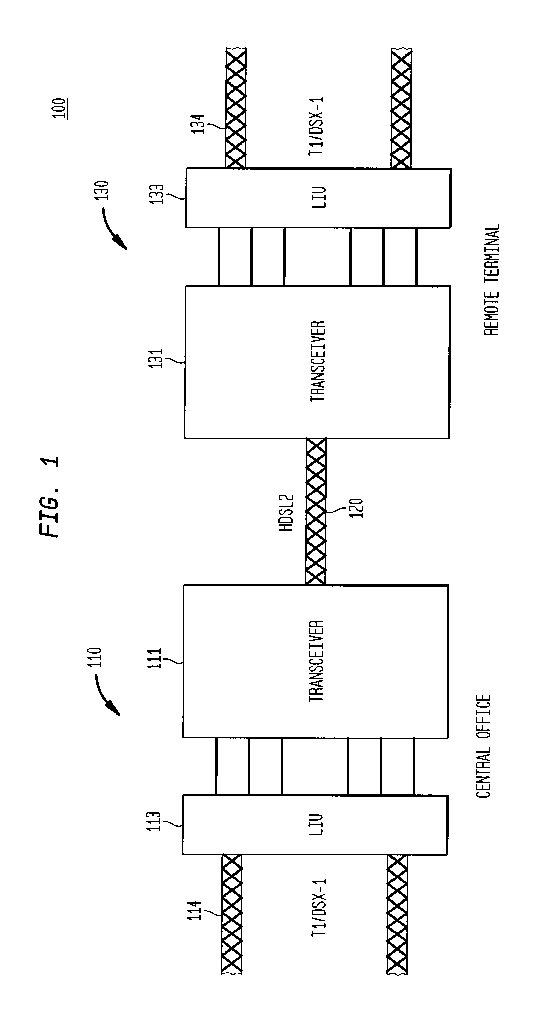
[0037]Referring initially to FIG. 1, illustrated is a system level diagram of an embodiment of a communications network, generally designated 100, within which an embodiment of a transceiver constructed according to the principles of the present invention may operate. The communications network 100 may form a portion of a larger communications network (e.g., the public switched telephone network) and may advantageously provide high-bit-rate digital subscriber line service over a single twisted pair wire (commonly referred to as HDSL2). The communications network 100 includes a central office 110 and a remote terminal 130. The central office 110 embodies any conventional or later developed switching system that facilitates communications over the communications network 100. The remote terminal 130 embodies any conventional or later developed communications device (e.g., a multimedia personal computer) adapted to communicate with the communications network 100. It should be understood...


PUM


Abstract

A separation circuit, method of determining a residual level of an echo, and an echo canceling system, bit pump and transceiver employing the circuit and method. The echo canceling system employing the separation circuit is couplable between a transmit and receive path of the bit pump and generates an echo canceling signal. In one embodiment, the separation circuit includes a symbol determination circuit that accepts a receive signal, propagating along the receive path, substantially free of an echo and determines a symbol associated with the receive signal. The separation circuit also includes an estimator stage, coupled to the symbol determination circuit, that receives the symbol and provides an estimated receive signal. The separation circuit generates data representing a residual level of the echo as a function of the estimated receive signal and the echo canceling signal.

Description

CROSS-REFERENCE TO RELATED APPLICATION[0001]This U.S. application is related to the following U.S. applications.[0002]ReferenceNumberFile DateTitleChadha 1-1-1-1Aug. 29, 2000FILTER CIRCUIT FORA BIT PUMP AND METHOD OFCONFIGURING THE SAMEChadha 2-2-2Aug. 29, 2000SEPARATION CIRCUIT FORAN ECHO CANCELING SYSTEMAND METHOD OF OPERATINGTHE SAMEChadha 3-3-1Aug. 29, 2000ECHO CANCELING SYSTEMFOR A BIT PUMP ANDMETHOD OF OPERATINGTHE SAMEBarnette 1Aug. 29, 2000AN INTERPOLATOR,A RESAMPLER EMPLOYINGTHE INTERPOLATOR ANDMETHOD OF INTERPOLATINGA SIGNAL ASSOCIATEDTHEREWITHBarnette 2-2Aug. 29, 2000RESAMPLING FOR A BITPUMP AND METHOD OFRESAMPLING A SIGNALASSOCIATED THEREWITHThe above-referenced U.S. applications are commonly assigned with the present invention and incorporated herein by reference.TECHNICAL FIELD OF THE INVENTION[0003]The present invention is directed, in general, to digital signal processing and, more specifically, to a separation circuit for an echo canceling system of a bit pump emplo...

Claims


Application Information

Patent Timeline
Patent Type & Authority Patents(United States)
IPC IPC(8): H04B3/23H04M1/76H04L1/00
CPCH04B3/23H04L25/03993H04L1/0054
Inventor CHADHA, MANDEEP SINGHMCCASLIN, SHAWN ROBERTMILISAVLJEVIC, MILE
Owner LUCENT TECH INC
Learn More