
X-ray measuring apparatus

Inactive Publication Date: 2005-05-17
HITACHI MEDICAL CORP
View PDF12 Cites 14 Cited by
  • Summary
  • Abstract
  • Description
  • Claims
  • Application Information

AI Technical Summary

Benefits of technology

[0025]An object of the present invention is to provide an x-ray measuring apparatus for diagnosis capable of obtaining a moiré-free image of a large field of view with high spatial resolution and high sensitivity.
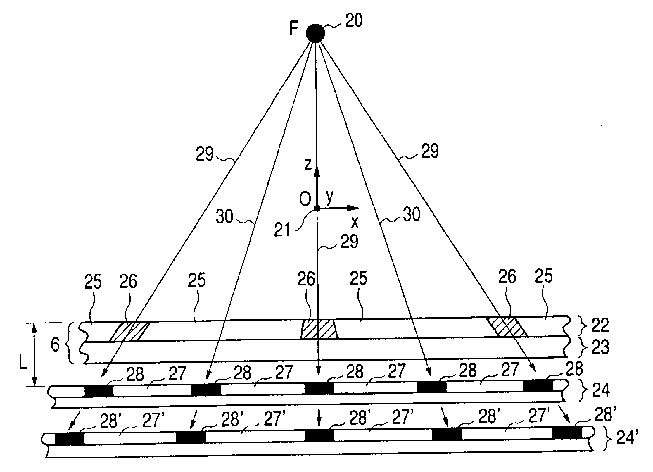
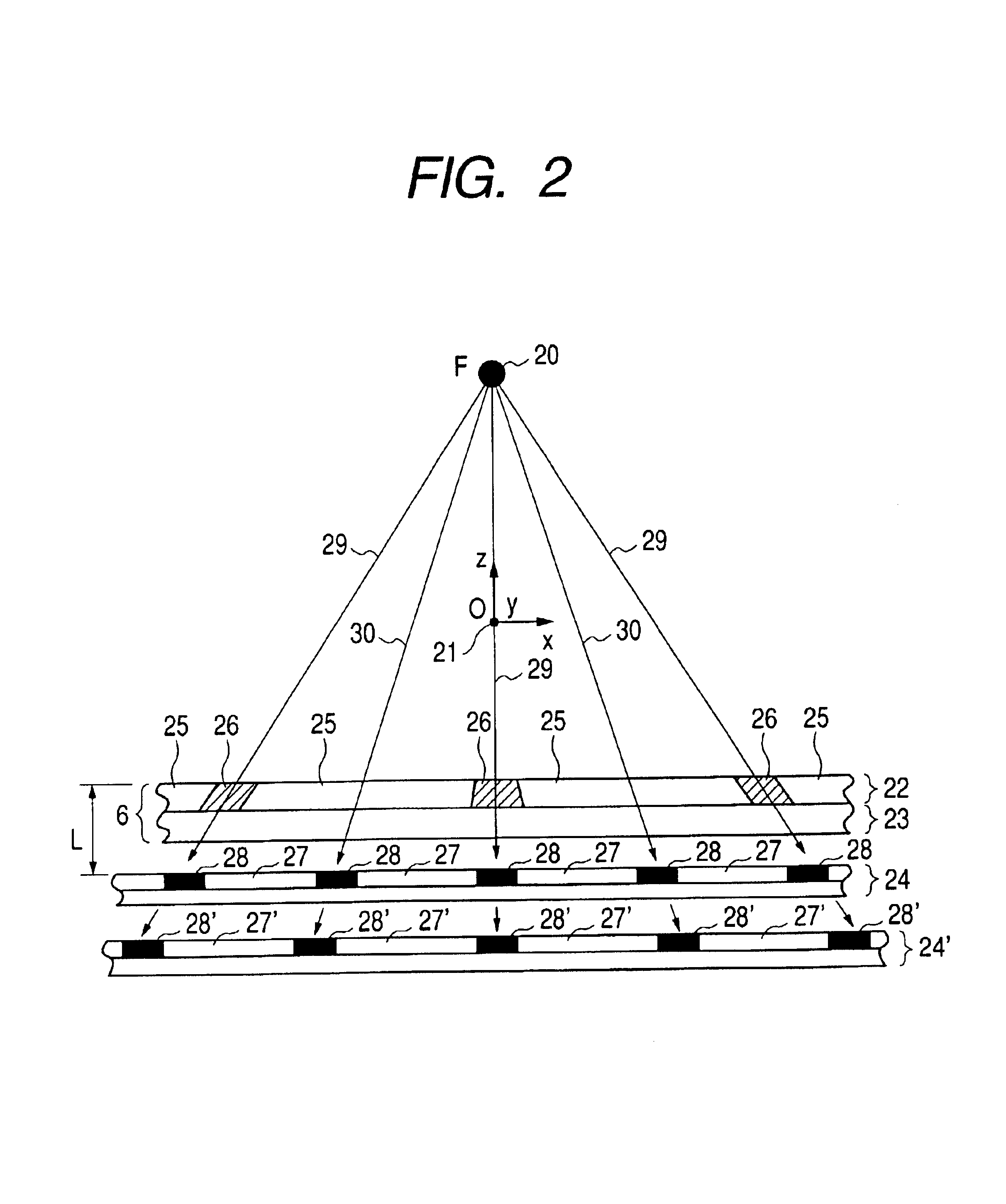
[0029]In a first configuration of the invention, the pitch in one direction of linear images of the x-ray shielding members of the anti-scatter grid projected on a sensing surface of the x-ray detector is set to be substantially an integral multiple of two or larger of the pitch of arrangement of the sensing elements in the one direction. With the configuration, a moiré-free image of a large field of view can be obtained with high spatial resolution and high sensitivity.
[0031]In the first configuration, the anti-scatter grid is disposed between the x-ray focal spot and the x-ray detector with a predetermined fixed distance from the position of the x-ray focal spot, and the x-ray measuring apparatus further includes adjusting means for adjusting the interval between the position of a surface formed by end portions on the x-ray incident surface side of the plurality of x-ray shielding members of the anti-scatter grid and the position of a sensing surface (surface on which a plurality of a-SiPDs are formed) of the x-ray detector in a direction connecting the x-ray focal spot and the center portion of the anti-scatter grid. The adjusting means can adjust the interval in a state where the surface formed by end portions on the x-ray incident surface side of the plurality of x-ray shielding members of the anti-scatter grid and the sensing surface of the x-ray detector is held substantially parallel to each other.
[0034]Further, the pitch in the first direction of the linear projection images on the sensing surface of the x-ray detector of the first x-ray shielding members and the pitch in the second direction of the linear projection images on the sensing surface of the x-ray detector of the second x-ray shielding members are substantially equal to each other. The anti-scatter grid constructed by the first and second scatter grids is a cross anti-scatter grid. Since the structure in which the x-ray shielding members of the anti-scatter grid are arranged two-dimensionally is used, interference of scattering x-rays is little, and a moiré-free image can be obtained with high spatial resolution and high sensitivity.
[0036]By irradiating the subject with radial x-rays from the x-ray focal spot, cone-beam CT measurement is performed and a moiré-free three-dimensional reconstructed image can be obtained with high spatial resolution and high sensitivity.
[0039]In addition, a pitch in the first direction of linear images projected on the sensing surface of the x-ray detector of the first x-ray shielding members and a pitch in the second direction of linear images projected on a sensing surface of the x-ray detector of the second x-ray shielding members are set to be substantially equal to each other. In a manner similar to the first configuration, an anti-scatter grid (cross anti-scatter grid) having x-ray shielding members arranged two-dimensionally is used, so that interference of scattering x-rays is little and a moiré-free image can be obtained with high spatial resolution and high sensitivity.

Problems solved by technology

In the case of using an x-ray detector, there is a problem such that deterioration in picture quality by scattering x-rays cannot be avoided.
It causes deterioration in sensitivity by the anti-scatter grid and a problem arises such that exposure of x-rays has to be increased to obtain predetermined sensitivity.
However, any of the above cases has a problem such that moiré occurs due to loss of the corresponding relation between the arrangement pitch of x-ray shielding members and the pitch in the sensing distribution of the x-ray detector.
In a cone-beam CT image, there is a problem such that degradation occurs in picture quality due to artifact caused by moiré and quantitativeness of a CT value deteriorates.

Method used


Image

  • X-ray measuring apparatus
  • X-ray measuring apparatus
  • X-ray measuring apparatus

Examples


Embodiment Construction

[0047]Embodiments of the invention will be described in detail hereinbelow with reference to the diagrams.

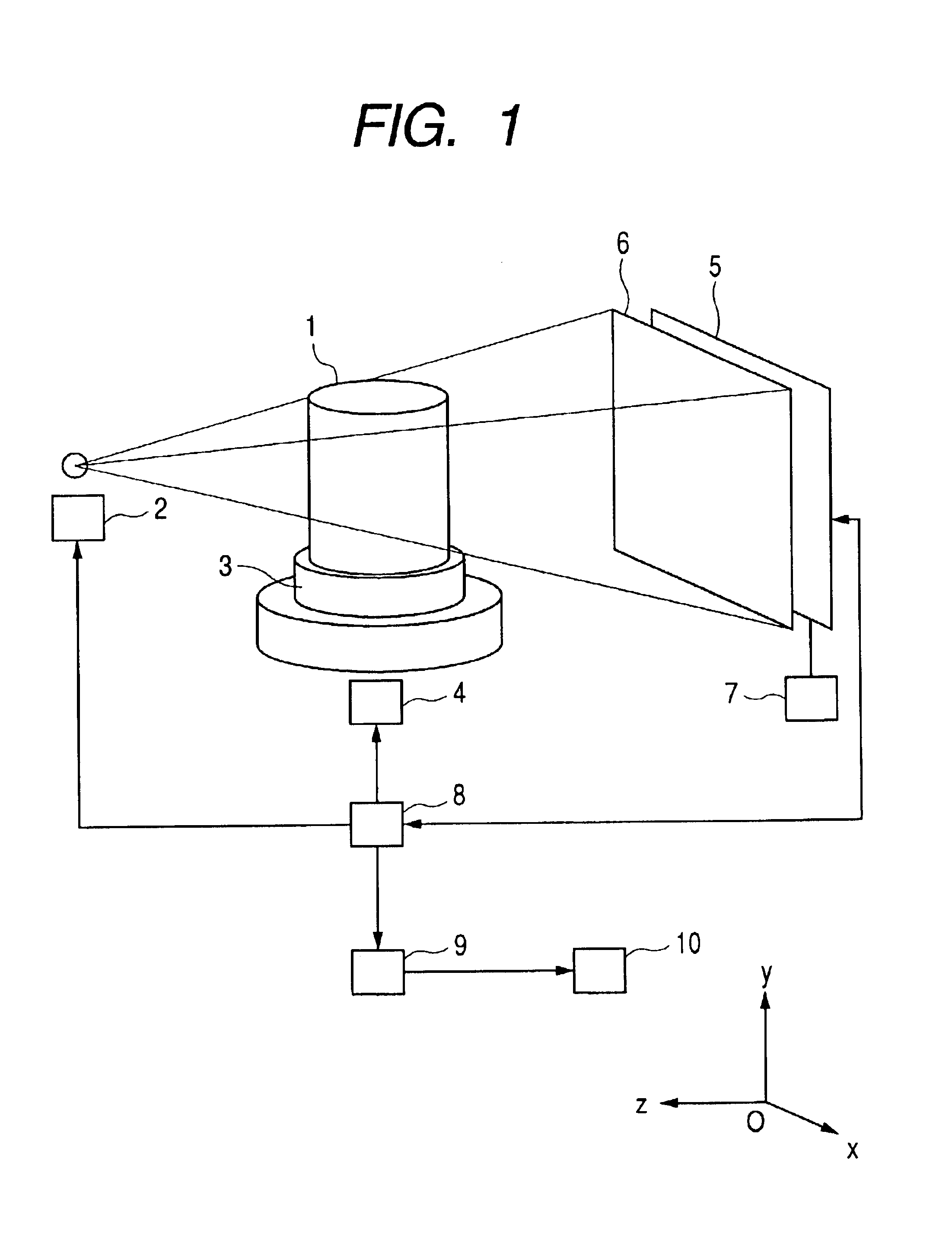
[0048]FIG. 1 is a diagram showing an example of the configuration of a cone-beam CT apparatus of an embodiment of the invention. The cone-beam CT apparatus includes an x-ray tube 2 for emitting x-rays to a subject 1, a table 3 for holding the subject 1, a rotating device 4 for rotating the table 3, an x-ray detector 5 for detecting x-rays passed through the subject 1, an anti-scatter grid 6 for blocking scattering rays, an adjustment device 7 for adjusting the position of the x-ray detector 5 relative to the anti-scatter grid 6, a data acquisition device 8 for acquiring output signals of sensing elements of the x-ray detector 5 by controlling the x-ray tube 2, rotating device 4, and x-ray detector 5, a data processing device 9 for performing a process of computing the acquired data, and a display 10 for displaying the acquired data and the result of the computing process. The da...


PUM


Abstract

The present invention provides an x-ray measuring apparatus for diagnosis having high spatial resolution and high sensitivity, which includes: an x-ray source for emitting x-rays from an x-ray focal spot; an x-ray detector in which a plurality of sensing elements each having a sensitive part and a blind part surrounding the sensitive part are arranged two-dimensionally; data processing means for collecting output signals of the sensing elements and performing data processing; and an anti-scatter grid disposed between the x-ray focal spot and the x-ray detector with predetermined distance from the position of the x-ray focal spot and in which an x-ray transmitting member and an x-ray shielding member are alternately arranged in a first direction. A pitch in the first direction of linear images projected on a sensing surface of the x-ray detector of the x-ray shielding member by the x-ray is set to be substantially an integral multiple of two or larger of the pitch of arrangement of the sensing elements in the first direction. In such a manner, a moiré-free image of a wide field of view is obtained.

Description

TECHNICAL FIELD[0001]The present invention relates to x-ray measuring apparatuses such as an x-ray image acquiring apparatus, an x-ray fluoroscopic apparatus, and a cone-beam computed tomographic (CT) apparatus capable of acquiring an image of a high picture quality by using a flat-type x-ray detector.BACKGROUND ART[0002]An x-ray fluoroscopic apparatus and an x-ray image acquiring apparatus for measuring an x-ray image by using a two-dimensional x-ray detector are known techniques. There are a cone-beam CT for performing image acquisition while rotating an x-ray source and a two-dimensional x-ray detector around the subject, and a cone-beam CT for performing image acquisition while fixing an x-ray source and a two-dimensional x-ray detector and rotating the subject (Japanese Patent Application Laid-Open No. 10-192267: prior art 1).[0003]In the cone-beam CT, by performing a correcting process on each of a plurality of images acquired by the rotation image acquisition, a set of projec...

Claims


Application Information

Patent Timeline
IPC IPC(8): G01N23/04G01N23/02G21K1/02G01T1/00G01T7/00
CPCG21K1/025G01N23/04
Inventor BABA, RIKAUEDA, KEN
Owner HITACHI MEDICAL CORP
Learn More