Rechargeable spinal cord stimulator system

a spinal cord stimulator and rechargeable technology, applied in the field of spinal cord stimulation systems, can solve the problems of limited battery life, force the patient to wear an external power source and controller, and not all of the above-described features are available in one device, so as to achieve reliable electrode/spinal cord relationship, prevent dislocation, and convenient implementation

Inactive Publication Date: 2005-05-17
BOSTON SCI NEUROMODULATION CORP
View PDF96 Cites 1424 Cited by
  • Summary
  • Abstract
  • Description
  • Claims
  • Application Information

AI Technical Summary

Benefits of technology

[0028]The lead extension (LEX) and electrode array (EA) comprises an electrode array having up to sixteen electrode contacts that may be independently activated by the IPG. The lead extension provides the connection between the IPG and the electrode array. In a preferred embodiment, up to two electrode arrays may be connected to the IPG. Features of the LEX and EA include: (a) the electrode array and lead extension provide the clinician with many options, e.g., one or two electrode arrays with only a single lead extension, (b) the lead

Problems solved by technology

Unfortunately, not all of the above-described features are available in any one device.
For example, one well-known device has a limited battery life at only modest current outputs, and has only a single voltage source, and hence only a single stimulation channel, which must be multiplexed in a fixed pattern to up to four electrode contacts.
Another well-known device off

Method used


Image

  • Rechargeable spinal cord stimulator system
  • Rechargeable spinal cord stimulator system
  • Rechargeable spinal cord stimulator system

Examples


Embodiment Construction

[0061]The following description is of the best mode presently contemplated for carrying out the invention. This description is not to be taken in a limiting sense, but is made merely for the purpose of describing the general principles of the invention. The scope of the invention should be determined with reference to the claims.

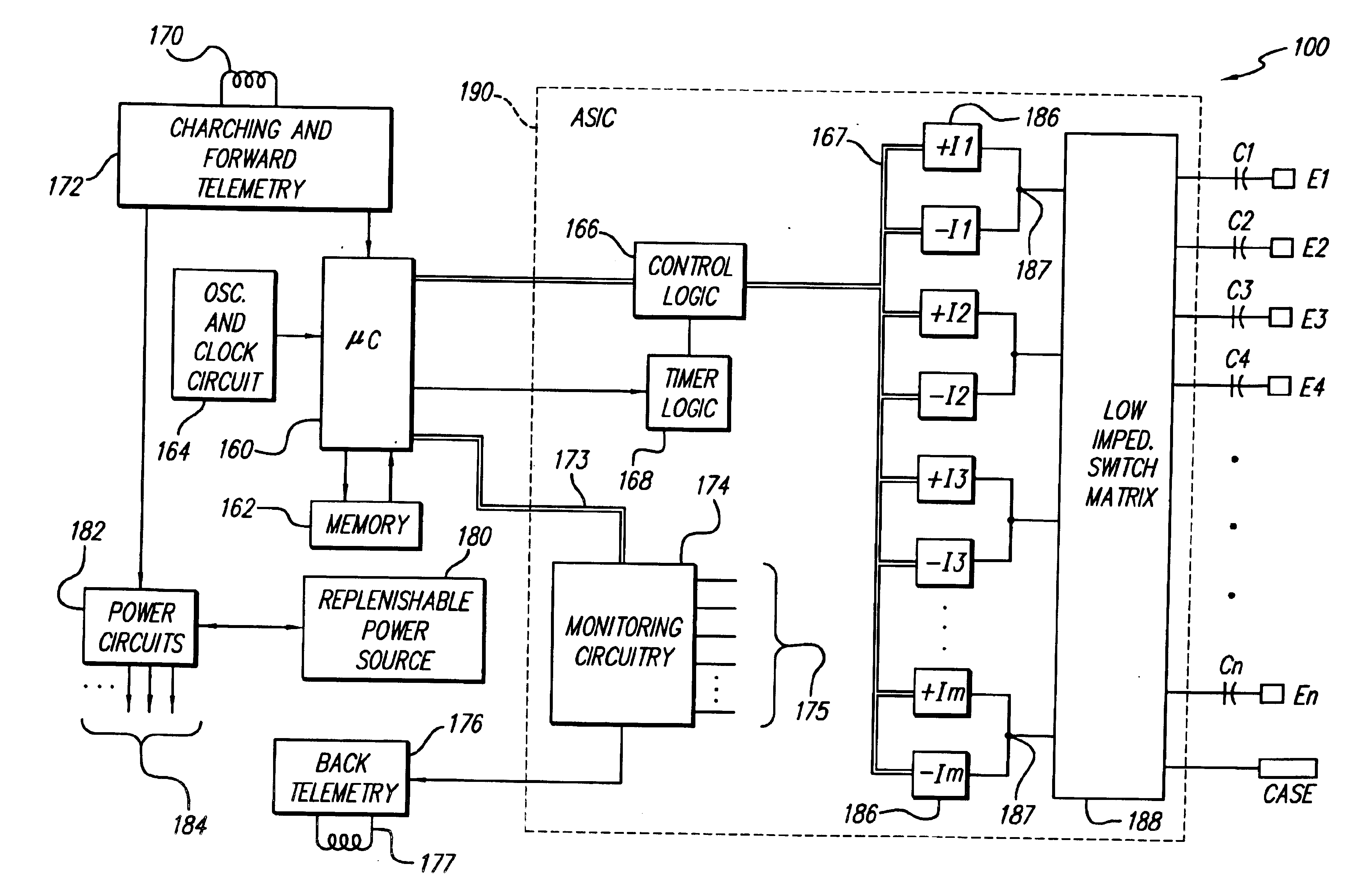
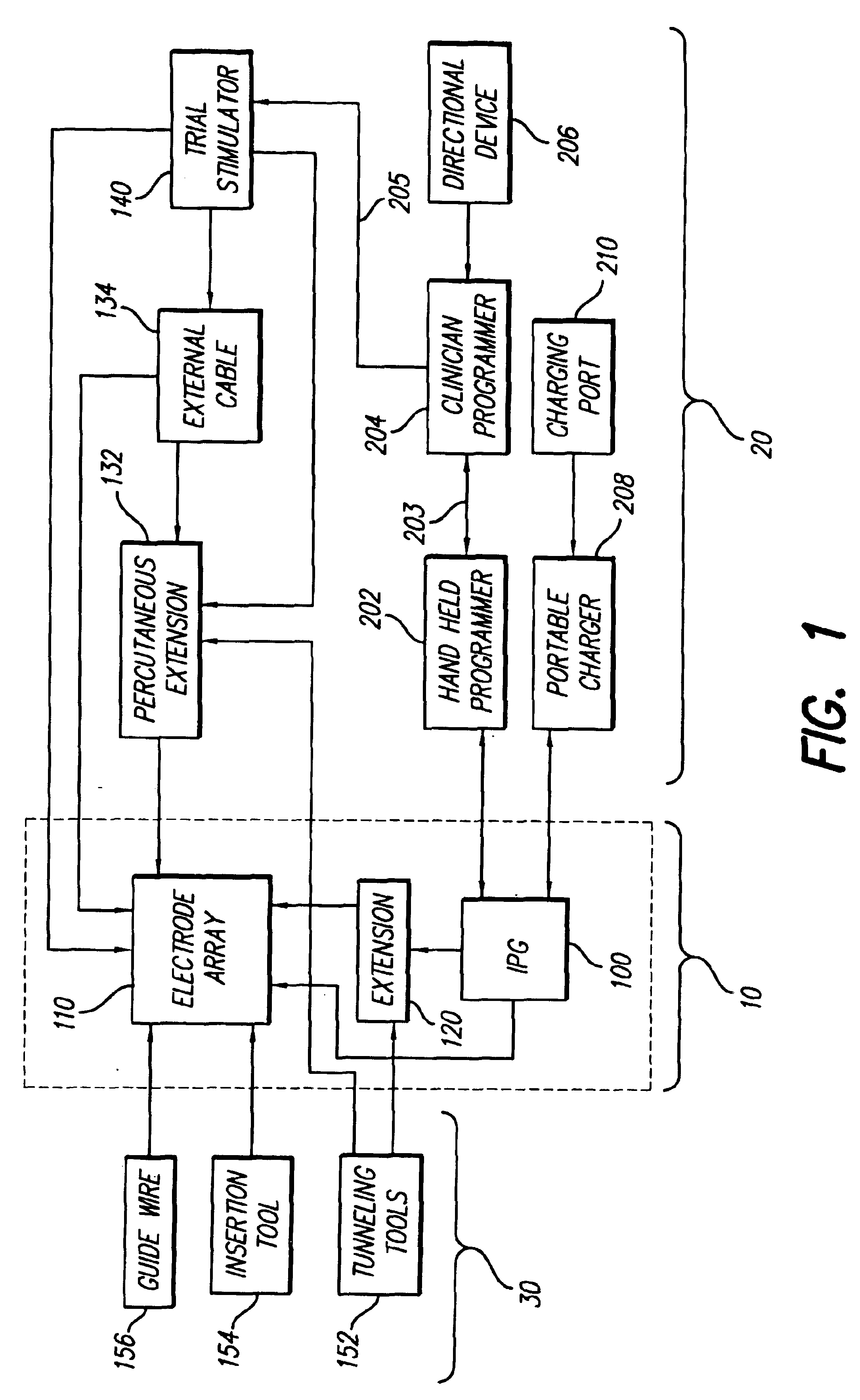
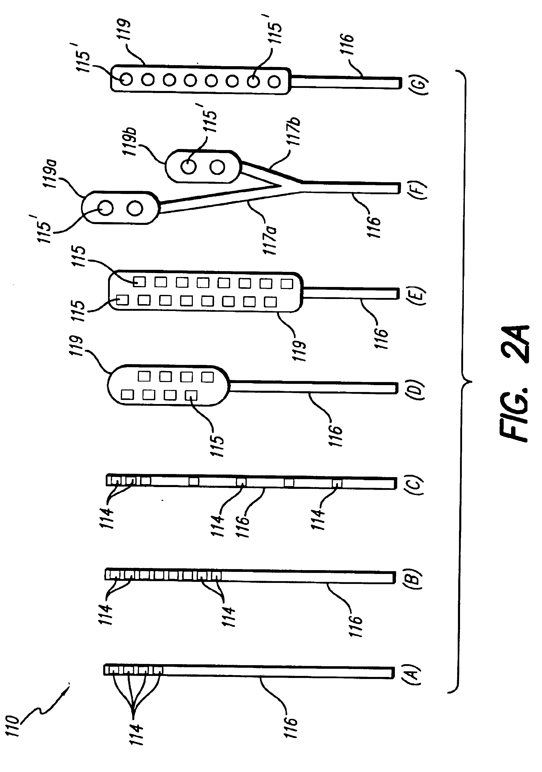
[0062]Turning first to FIG. 1, there is shown a block diagram that illustrates the various components of a spinal cord stimulation (SCS) system. These components may be subdivided into three broad categories: (1) implantable components 10, (2) external components 20, and (3) surgical components 30. As seen in FIG. 1, the implantable components 10 include an implantable pulse generator (IPG) 100, an electrode array 110, and (as needed) an extension 120. The extension 120 is used to electrically connect the electrode array 110 to the IPG 100. In a preferred embodiment, the IPG 100, described more fully below in connection with FIGS. 4A, 4B and 4C, comprises a ...


PUM


Abstract

A spinal cord stimulation (SCS) system includes multiple electrodes, multiple, independently programmable, stimulation channels within an implantable pulse generator (IPG) which channels can provide concurrent, but unique stimulation fields, permitting virtual electrodes to be realized. The SCS system includes a replenishable power source (e.g., rechargeable battery), that may be recharged using transcutaneous power transmissions between antenna coil pairs. An external charger unit, having its own rechargeable battery can be used to charge the IPG replenishable power source. A real-time clock can provide an auto-run schedule for daily stimulation. An included bi-directional telemetry link in the system informs the patient or clinician the status of the system, including the state of charge of the IPG battery. Other processing circuitry in the IPG allows electrode impedance measurements to be made. Further circuitry in the external battery charger can provide alignment detection for the coil pairs.

Description

[0001]The present invention is a continuation of U.S. application Ser. No. 09 / 626,010, filed Jul. 28, 2000, issued as U.S. Pat. No. 6,516,227, which claims the benefit of U.S. Provisional Application Serial No. 60 / 145,829, filed Jul. 27, 1999. U.S. Pat. No. 6,516,277 and the Provisional application are herein incorporated by reference.[0002]The present invention relates to a spinal cord stimulation system for stimulating nerves in the spinal cord.BACKGROUND OF THE INVENTION[0003]The present invention relates to a Spinal Cord Stimulation System. A spinal cord stimulation system is a programmable implantable pulse generating system used to treat chronic pain by providing electrical stimulation pulses from an electrode array placed epidurally near a patient's spine. The present invention emphasizes the following specific features included within a spinal cord stimulation system: (1) a recharging system, (2) a system for mapping current fields, (3) optional pulse ramping control, and (4...

Claims


Application Information

Patent Timeline
IPC IPC(8): A61N1/32A61N1/05A61N1/372A61N1/34A61N1/378A61N1/36H01H85/20H01H85/32H05K7/02
CPCA61N1/0553A61N1/36071A61N1/36185H01H85/32A61N1/37252A61N1/3787H01H85/201A61N1/37247A61N1/37241
Inventor MEADOWS, PAUL M.WOODS, CARLA MANNPETERSON, DAVID K.CHEN, JOEYPAYNE, DAVID H.
Owner BOSTON SCI NEUROMODULATION CORP
Why Eureka
Try Eureka