Tamper detection system for securing data

a data and detection system technology, applied in the field of data protection systems, to achieve the effect of simple operation

Inactive Publication Date: 2005-05-17
PITNEY BOWES INC
View PDF28 Cites 72 Cited by
  • Summary
  • Abstract
  • Description
  • Claims
  • Application Information

AI Technical Summary

Benefits of technology

[0005]In the most preferred embodiments, the present invention provides a tamper detection system that includes a trigger mechanism system and a detection circuit that operate in combination to protect an integrated circuit from attack. The detection circuit connects to the trigger mechanism system that is basically a protective mesh that consists of two separate loops of wire held in close proximity to each other and an optional ground layer. The mesh is such that any attempted penetration is highly likely to cause an open of either loop or a short of one loop to the other. The detection system recognizes shorts and opens in the mesh. The detection circuit is intended to be very simple in its operation in that it does not require a sophisticated stimulus and response set to operate. It is designed to be polled on a regular basis for indications of a change in its operation.

Problems solved by technology

The mesh is such that any attempted penetration is highly likely to cause an open of either loop or a short of one loop to the other.

Method used


Image

  • Tamper detection system for securing data
  • Tamper detection system for securing data

Examples


Embodiment Construction

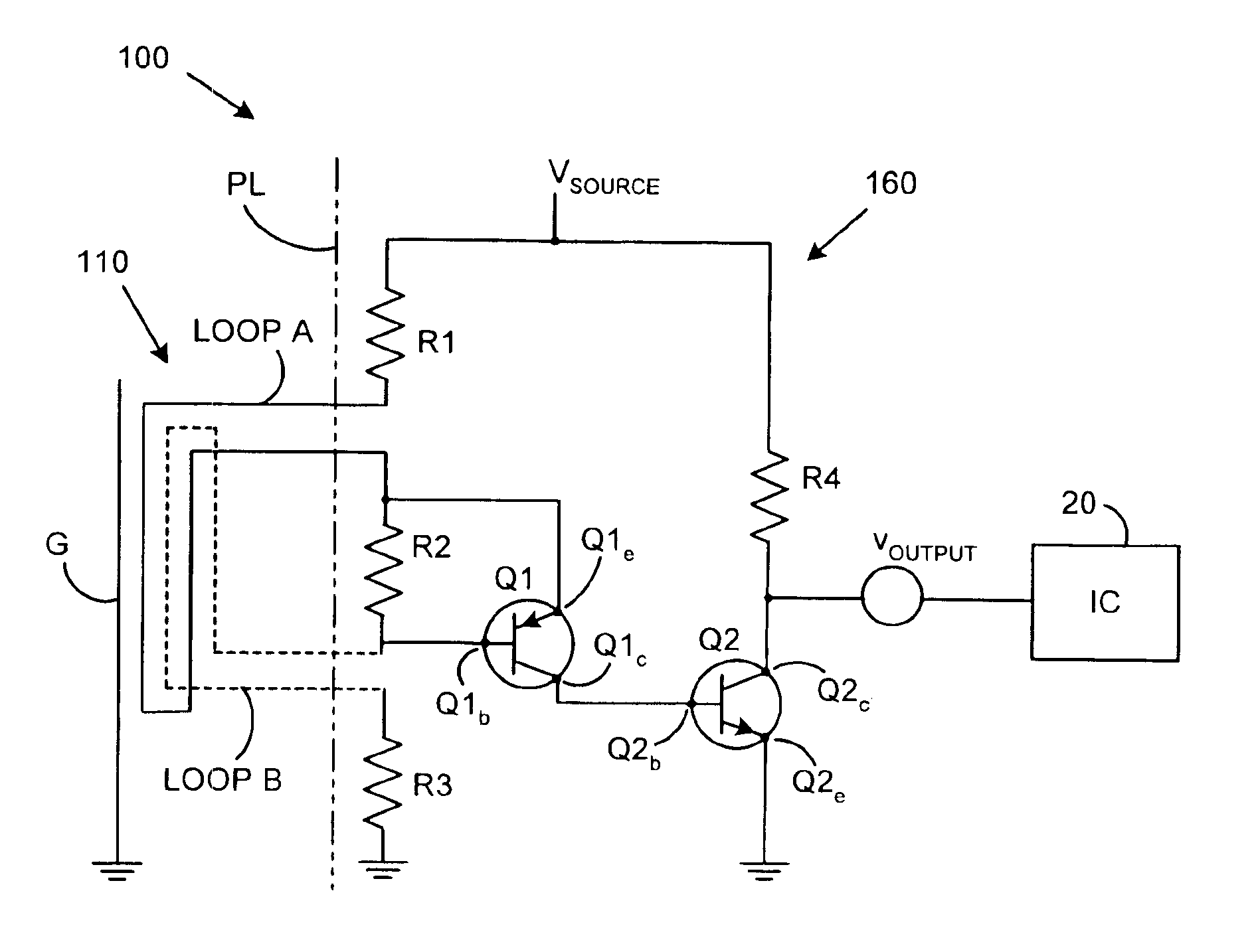
[0011]Referring to FIG. 1, a tamper detection system 100 in combination with a protected integrated circuit 20 that it protects is shown. The tamper detection system 100 includes a trigger circuit 110 and a detection circuit 160. Generally, the trigger circuit 110 is shown to the left of the phantom line PL while the detection circuit 160 is shown to the right. It should be understood that the phantom line PL does not constitute part of the present invention, but is merely used to illustrate the geometric relationship between the trigger circuit 110 and the detection circuit 160. Those skilled in the art will recognize that the distinction between the elements that have been designated are part of the trigger circuit 110 and the detection circuit 160, respectively, is subject to interpretation. However, as a general rule, the elements that an intruder would initially come into contact with during a tamper attempt have been designated as the trigger circuit 110 while the remaining po...


PUM


Abstract

A tamper detection system includes a trigger mechanism system and a detection circuit that operate in combination to protect an integrated circuit from attack. The detection circuit connects to the trigger mechanism system that is basically a protective mesh that consists of two separate loops of wire held in close proximity to each other and an optional ground layer. The mesh is such that an attempted penetration is highly likely to cause an open of either loop or a short of one loop to the other. The detection system recognizes shorts and opens in the mesh. The detection circuit is intended to be very simple in its operation it that it does not require a sophisticated stimulus and response set to operate. It is designed to be polled on a regular basis for indications of a change in its operation.

Description

FIELD OF THE INVENTION[0001]This invention relates generally to data protection systems. More particularly, in the preferred embodiments, this invention is directed to a tamper detection system for detecting unauthorized attempts to access an integrated circuit.BACKGROUND OF THE INVENTION[0002]In many different industries, there is a need to protect data (information) from discovery. Oftentimes, the data is resident within the discrete electronic components of an integrated circuit. In turn, the integrated circuit may be incorporated into a printed circuit board, a smart card or other electronic device. The data itself may be of a wide variety depending upon the particular industry. As examples, the data may be used in: monetary transactions (debit card, postage metering, etc.) and controlled access systems (security badges). Furthermore, the data may be cryptographic keys, account balances, some combination of these or any other type of data that is to be protected.[0003]Because of...

Claims


Application Information

Patent Timeline
Patent Type & Authority Patents(United States)
IPC IPC(8): G06F11/30G06F12/14H01L23/58H04L9/00H04L9/32H04L17/00H04L17/02G06F21/00G06K19/073
CPCG06F21/87G06K19/07372H01L23/576H01L2924/3011H01L2924/0002Y10S257/922H01L2924/00Y04S40/20
Inventor CLARK, DOUGLAS A.
Owner PITNEY BOWES INC
Why Eureka
Try Eureka