Dual motor strapper

a dual-motor, strapper technology, applied in the direction of manufacturing tools, bundling machine details, packaging goods types, etc., can solve the problems of increasing the size and weight of the tool, inconsistent strap tension and welds, and the tool is extremely difficult to remove without damaging the strap

Inactive Publication Date: 2005-05-24
SIGNODE IND GRP
View PDF10 Cites 8 Cited by
  • Summary
  • Abstract
  • Description
  • Claims
  • Application Information

AI Technical Summary

Benefits of technology

[0027]To effect articulation, the guide includes an elongated slot and the strapping tool includes a pin extending therefrom for engaging the slot. The pin is fixed relative to the pivotal movement of the tensioning motor housing. The pin engages the slo

Problems solved by technology

As will be recognized by those skilled in the art, known pneumatic strapping tools require many system components that increase the size and weight of the tool.
In addition, even though the pneumatic circuit of the above-mentioned U.S. Pat. No. 5,380,393 automates many strapping operations otherwise performed manually, controll

Method used


Image

  • Dual motor strapper
  • Dual motor strapper
  • Dual motor strapper

Examples


Embodiment Construction

[0044]While the present invention is susceptible of embodiment in various forms, there is shown in the drawings and will hereinafter be described a presently preferred embodiment with the understanding that the present disclosure is to be considered an exemplification of the invention and is not intended to limit the invention to the specific embodiment illustrated.

[0045]It should be further understood that the title of this section of this specification, namely, “Detailed Description Of The Invention”, relates to a requirement of the United States Patent Office, and does not imply, nor should be inferred to limit the subject matter disclosed herein.

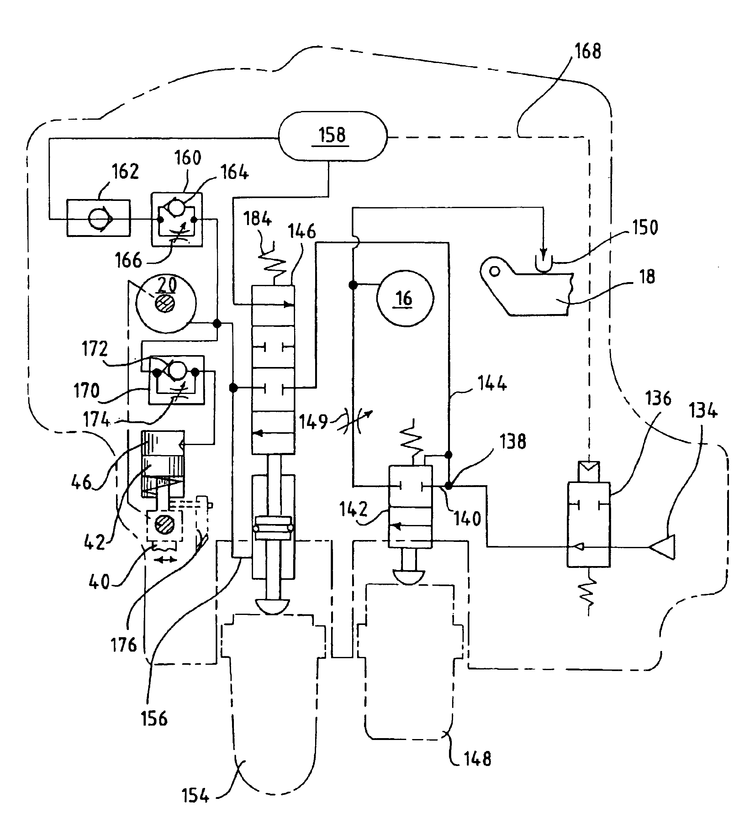
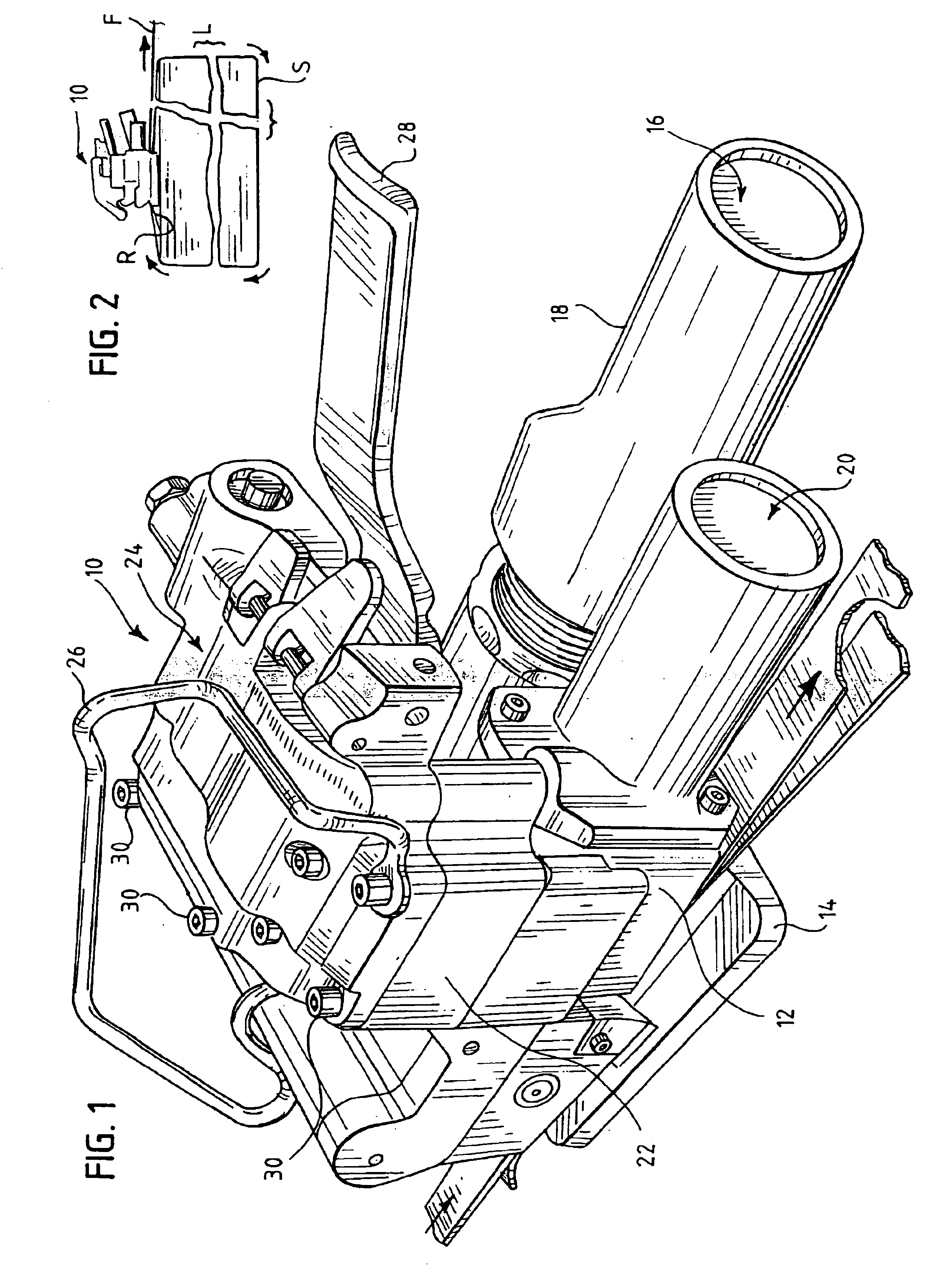
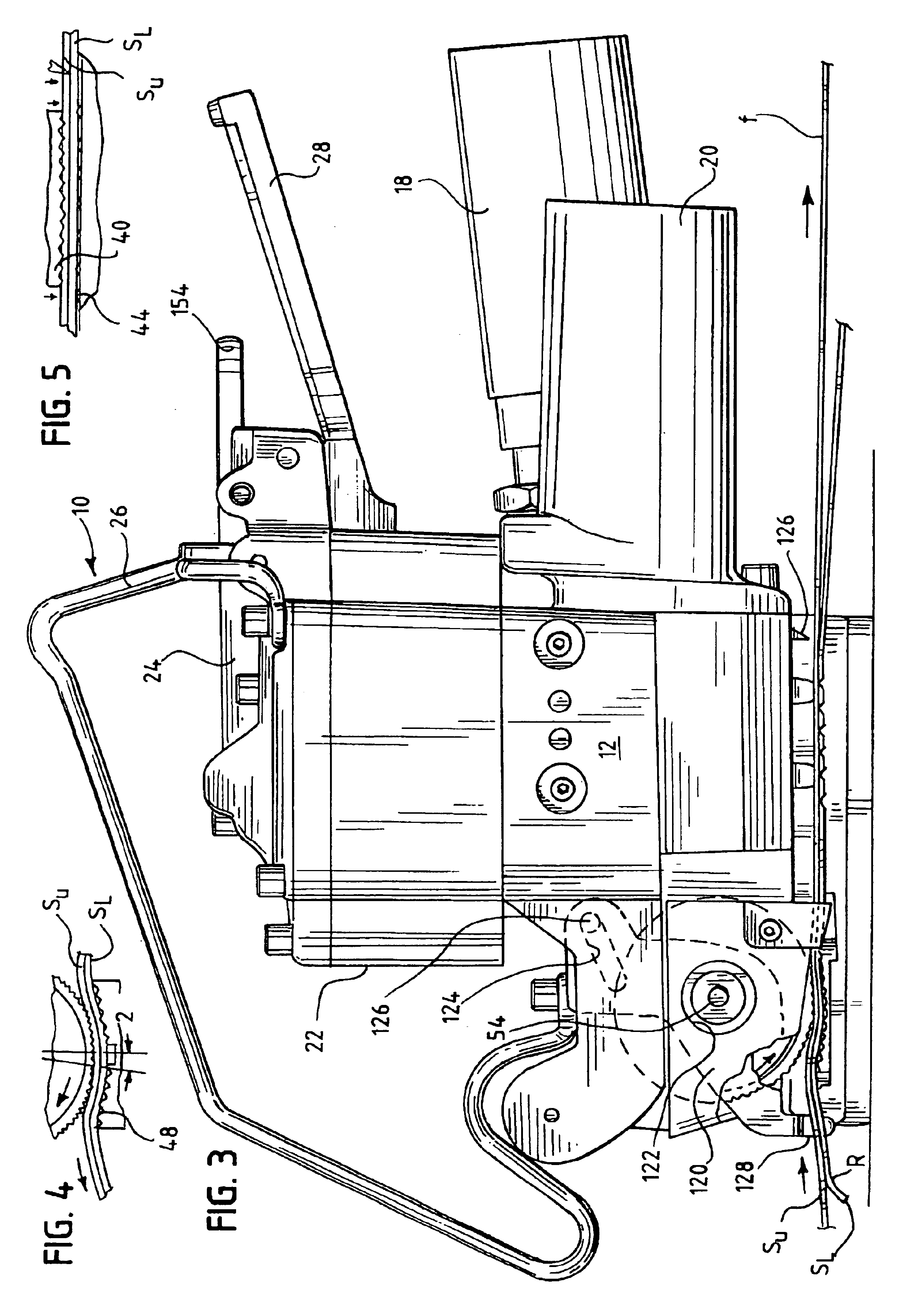
[0046]Referring now to the figures and in particular to FIGS. 1 and 2, there is shown a dual pneumatic motor strapper or strapping tool 10 embodying the principles of the present invention. The tool 10 is configured to tension a strap S around a load L, weld the strap material S onto itself and sever a feed end F of the strap S. For purp...


PUM

PropertyMeasurementUnit
Pressureaaaaaaaaaa
Flow rateaaaaaaaaaa

Abstract

A pneumatic strapping tool for tensioning a strap around a load, adhering the strap onto itself, and cutting a feed end of the strap includes a piston, a weld motor operably connected to the piston and a vibrating weld element operably connected to the piston for contacting the strap and adhering the strap onto itself. A tensioning motor is configured for unidirectional rotation. A feed wheel is operably connected to the tensioning motor by a drive assembly to tension the strap prior to adhering the strap onto itself. A transmission cooperates with the drive assembly and is switchable between a first state in which the transmission engages the drive assembly to permit only one-way rotation of the drive assembly and a second state in which the transmission permits two-way rotation of the drive assembly. The strapping tool includes a self-contained pneumatic module that is removably mounted to a cylinder housing. The module includes a compressed gas inlet, a plurality of valves and passageways between the inlet and the valves to provide compressed gas to the cylinder housing, a pneumatic weld motor and the pneumatic tensioning motor. The module includes at least one timer for operation of the weld motor and for providing pressure to the cylinder. An articulating guide is disposed at the strap path and moves between an open path position when the tensioning motor housing is pivoted to the loading/unloading position and a closed path position when the tensioning motor housing is pivoted to the strap engaging position. The guide aligns the strap with a second strap to which the strap it is adhered and aligns the straps with the feed wheel and anvil.

Description

CROSS-REFERENCE TO RELATED APPLICATION DATA[0001]This application is a divisional application of U.S. patent application Ser. No. 10 / 171,890, filed Jun. 14, 2002.BACKGROUND OF THE INVENTION[0002]The present invention pertains to an improved tool for tightening a strap around an object or load and adhering the strap onto itself. More particularly, the present invention is directed to a dual pneumatic motor tool for tensioning a strap around a load and welding or melt-adhering the strap onto itself.[0003]Strapping tools are well-known in the art. These tools come in a wide variety of types, from fully manual tools to automatic, table-top tools. These tools are generally specifically designed for use with metal strapping or plastic / polymeric type strapping.[0004]Typically, strappers for applying plastic or polymeric strapping materials are automatic table-top or hand-held devices. This is generally necessary in order to provide energy for adhering the strapping material onto itself. Ty...

Claims


Application Information

Patent Timeline
IPC IPC(8): B65B13/18B65B13/32B29C65/06B65B13/22B65B1/28
CPCB65B1/28B65B13/188B65B13/327B65B13/18B29C65/06B29C66/1122B29C66/4324B29C66/4322B25B33/00
Inventor NIX, ROBERT J.
Owner SIGNODE IND GRP
Why Eureka
Try Eureka