Premix burner and method of operation

a burner and pre-mix technology, applied in the direction of engine starters, engine/propulsion engine ignition, lighting and heating apparatus, etc., can solve the problems of high exhaust gas values, and emission of unsaturated hydrocarbons and the extinction limit, so as to achieve low exhaust gas emissions, high stability requirements, and high stability

Inactive Publication Date: 2005-05-24
ANSALDO ENERGIA SWITZERLAND AG
View PDF16 Cites 20 Cited by
  • Summary
  • Abstract
  • Description
  • Claims
  • Application Information

AI Technical Summary

Benefits of technology

[0010]Accordingly, one object of the invention is to improve a premix burner in such a way that the drawbacks which have been mentioned above in connection with the prior art no longer occur or only appear to a considerably reduced degree. In particular, the aim is to design a premix burner in such a manner that the operating range of the burner is distinguished by a high level of stability even under low load conditions, i.e. flashback of the backflow zone into the region of the premix burner is to be virtually completely eliminated. In particular, the aim is to configure the premix burner in such a manner that, despite high stability requirements and low exhaust-gas emissions, the premix burner is easy and inexpensive to adapt to different burner conditions. For example, it is intended in particular to ensure that the premix burner can be matched to individual burner conditions in a structurally simple manner and at the lowest possible cost.

Problems solved by technology

This means that the larger the backflow zone is designed to be, the greater the carbon oxide emissions, the emissions relating to unsaturated hydrocarbons and the extinction limit become.
If the above-described premix burner is supplied with premix gas uniformly along the premix holes, i.e. as part of a single-stage premix mode, stability problems result within the backflow zone which forms and the associated flame front if the fuel mass flow drops, for example when the gas turbine is operated in the lower load range.
The instability which then occurs can extinguish the flame.
However, a pilot mode of this nature leads to the formation of a diffusion flame, with the result that very high exhaust-gas values, in particular very high NOx emissions, are reached.
If the premix burner is operated in what is known as mixed mode, which is distinguished by fuel being injected both through the premix stage and through the pilot stage, combustion chamber pulsations increasingly occur in addition to the abovementioned increased exhaust-gas values, increasing the risk of a flashback into the premix burner region.

Method used


Image

  • Premix burner and method of operation
  • Premix burner and method of operation
  • Premix burner and method of operation

Examples


Embodiment Construction

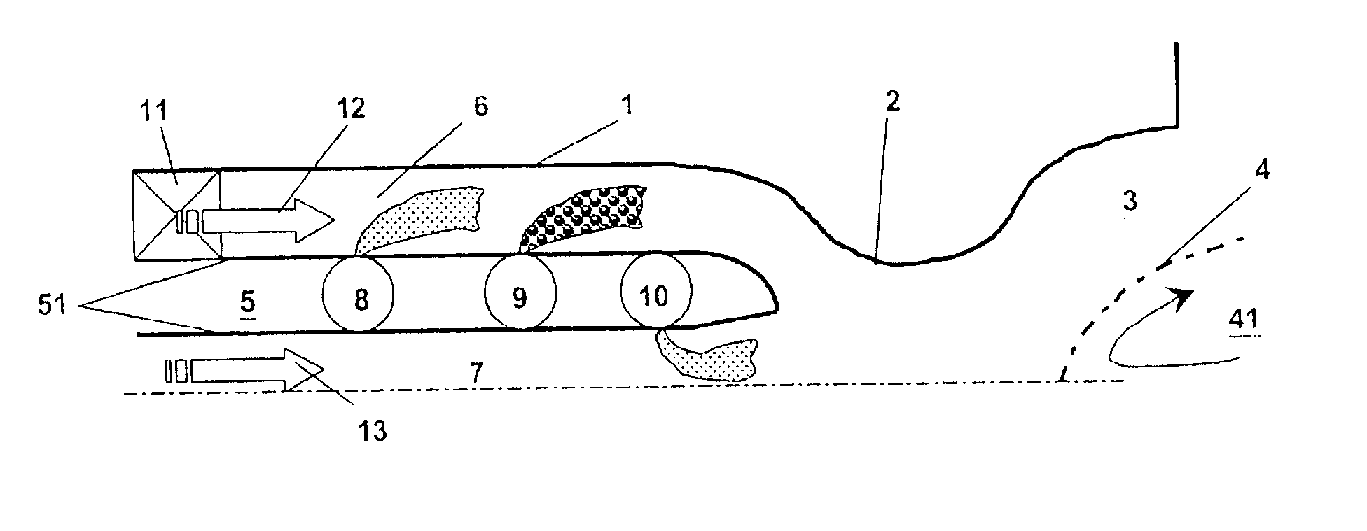
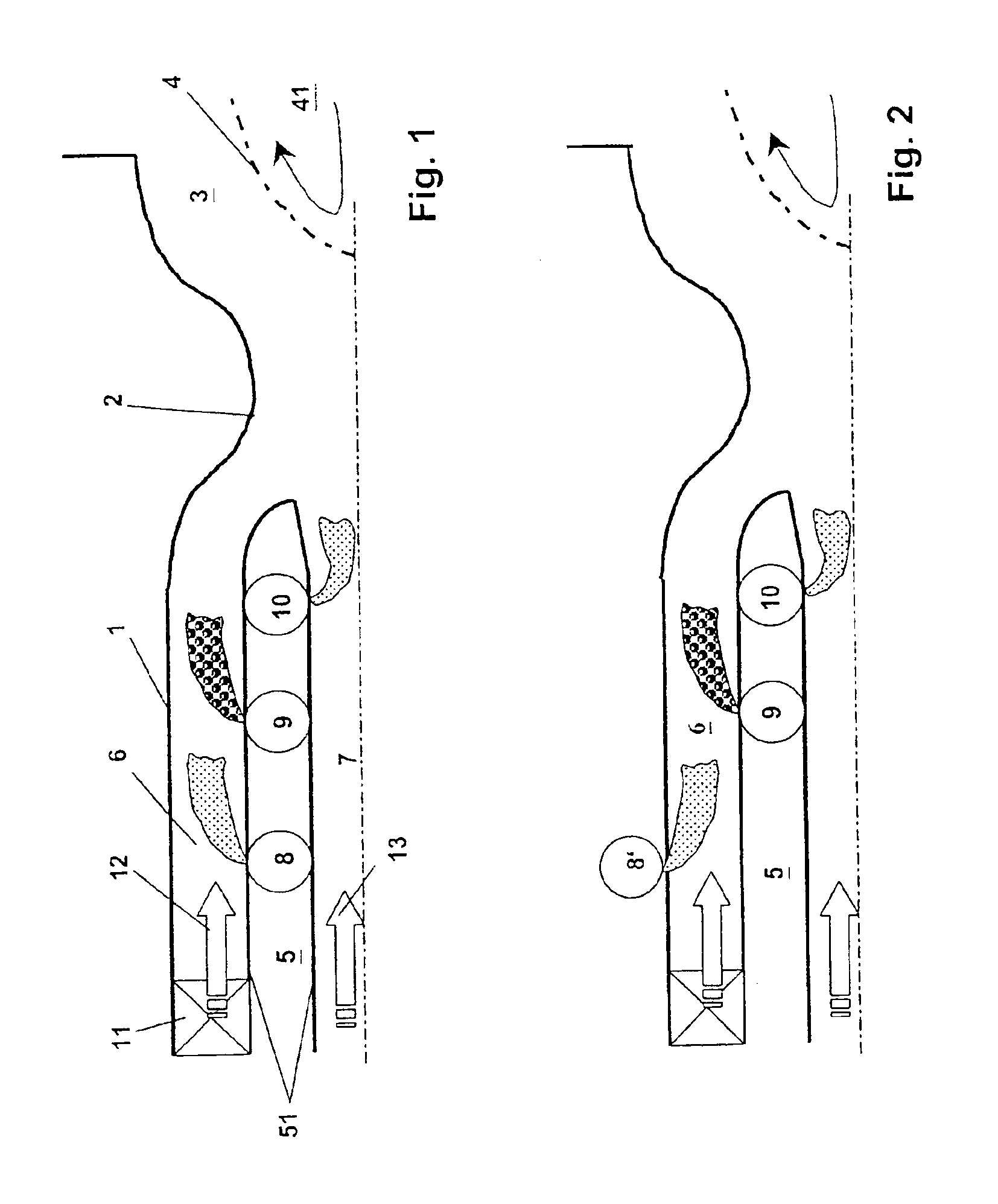
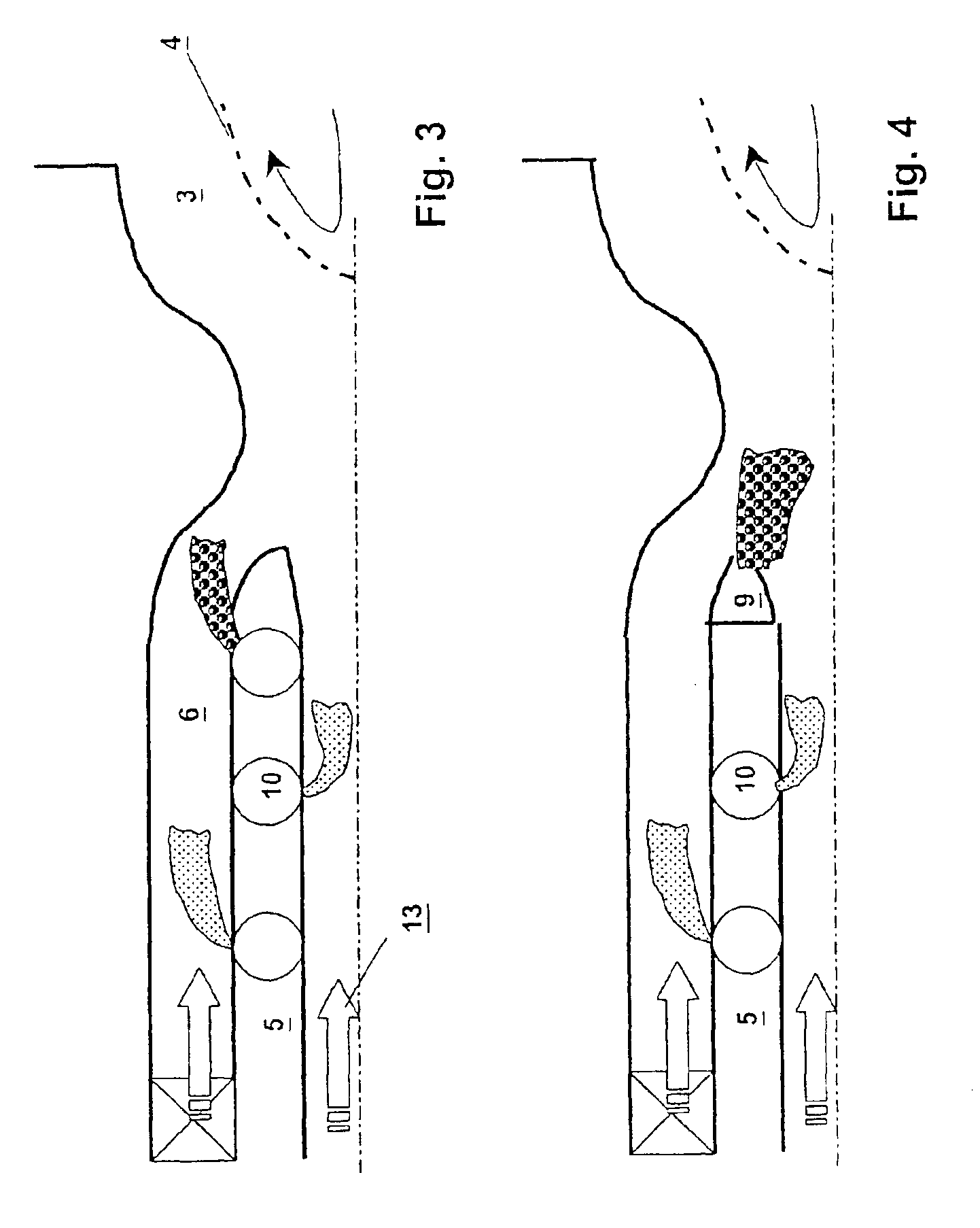
[0041]Referring now to the drawings, wherein like reference numerals designate identical or corresponding parts throughout the several views, all the figures illustrate longitudinal-section images through the premix burner structure, whose walls included in the drawing form rotationally symmetrical bodies, which means that in all the figures only the top half of the longitudinal section is illustrated and described.

[0042]FIG. 1, like all FIGS. 1 to 9, illustrates a tubular premix burner casing 1 which is designed to be open at its left-hand end as seen in the drawing. Feed air 12, 13 always flows through the premix burner casing 1 from the left to the right in the plane of the drawing. The premix burner casing 1 is axially followed in the direction of flow by a transition contour 2 which narrows the cross section of flow of the premix burner casing in the manner of a venturi nozzle. The region of the transition contour 2 which widens again in the cross section of flow is seamlessly ...


PUM


Abstract

A premix burner has a premix burner casing which is formed in the manner of a tube open at the upstream end, is connected in the downstream direction to a combustion chamber via a transition contour and through which air can flow, a burner lance including an inner tube that projects into the interior of the premix burner casing on the upstream side, encloses a flow passage which is annular in cross section together with the premix burner casing, and has an inner tube wall which surrounds an inner flow passage and in which there is at least one fuel-addition unit for feeding fuel into the inner flow passage and at least one further fuel-addition unit for feeding fuel into the annular flow passage is provided so that downstream of the inner tube the fuel/air mixture ignites within the flame front in the region of the combustion chamber.

Description

[0001]This application is a continuation of and claims priority under 35 U.S.C. §120 to International Application No. PCT / IB02 / 00384, filed Feb. 1, 2002, published as WO 02 / 061339 on Aug. 8, 2002 in German, and this application claims priority under 35 U.S.C. §119 to German application number 101 04 695.2, filed Feb. 2, 2001; the entireties of both of the aforementioned applications are incorporated by reference herein.BACKGROUND OF THE INVENTION[0002]1. Field of the Invention[0003]The invention relates to a premix burner for producing a homogeneously distributed fuel-air mixture for firing a combustion chamber which is used to drive a gas turbine which follows the combustion chamber.[0004]2. Discussion of Background[0005]The technique known as premix combustion has established itself in the combustion of liquid or gaseous fuel in a combustion chamber of a gas turbine. In this process, fuel and combustion air are premixed as uniformly as possible and are then passed into the combust...

Claims


Application Information

Patent Timeline
Patent Type & Authority Patents(United States)
IPC IPC(8): F23D17/00F23R3/14F23R3/28F23R3/04F23R3/34
CPCF23D17/002F23R3/14F23R3/343F23R3/286F23R2900/03343
Inventor KNOEPFEL, HANS PETER
Owner ANSALDO ENERGIA SWITZERLAND AG
Why Eureka
Try Eureka