Fuel injector and diesel engine comprising the same

a fuel injector and diesel engine technology, applied in the direction of fuel injection with fuel accumulator, fuel injection apparatus, fuel feed system, etc., can solve the problems of diesel engine stopping and valve mechanism change, increasing the amount of nox contained in exhaust gas, and environmental problems, so as to reduce the amount of nox and reduce the amount of smok

Inactive Publication Date: 2005-05-24
MITSUBISHI HEAVY IND ENGINE & TURBOCHARGER LTD
View PDF24 Cites 11 Cited by
  • Summary
  • Abstract
  • Description
  • Claims
  • Application Information

AI Technical Summary

Benefits of technology

[0010]In consideration of the above-described problems with conventional technology, an object of the present invention is to provide a fuel injector and a diesel engine comprising the fuel injector, which can solve both problems in the reduction of the smoke emission during low load and the decrease of NOx during high load.
[0011]In addition, in consideration of the above-described problems with conventional technology, another object of the present invention is to provide a fuel injector and a diesel engine comprising the fuel injector, in which the valve mechanism can be changed without the diesel engine being stopped.
[0012]Furthermore, in consideration of the above-described problems with conventional technology, another object of the present invention is to provide a fuel injector and a diesel engine comprising the fuel injector, in which a conventional mechanical fuel injection valve which can complete a fuel injection without delay, is used and the fuel injection rate is reliably controlled. That is, the object of the present invention is to provide a fuel injector and a diesel engine comprising the fuel injector, in which a fuel injection valve, which is constrained to the direction leading the needle valve to close by a spring, and when a fixed pressure is applied to the needle valve and the applied pressure is larger than the constrained force, the needle valve is opened, and thereby the fuel injection rate is reliably controlled, can be used.

Problems solved by technology

However, at the early period of a fuel injection during high load, since a large amount of fuel is injected, the amount of NOx contained in exhaust gas increases, and environmental problems may occur.
In addition, in the diesel engine comprising this fuel injector, when the valve mechanism is broken and the diesel engine does not operate, the diesel engine must be stopped and the valve mechanism must be changed.
Therefore, for example, when the diesel engine is used for generating electric power, during the change operation, electric power is temporarily not supplied.
In addition, when the diesel engine is a main engine of a ship, the ship is temporarily crippled.
Due to this, a fuel injection is not completed immediately and late combustion phase becomes worse.
Thereby, a problem arises in that an exhaust gas temperature and fuel consumption increase.

Method used


Image

  • Fuel injector and diesel engine comprising the same
  • Fuel injector and diesel engine comprising the same
  • Fuel injector and diesel engine comprising the same

Examples


first embodiment

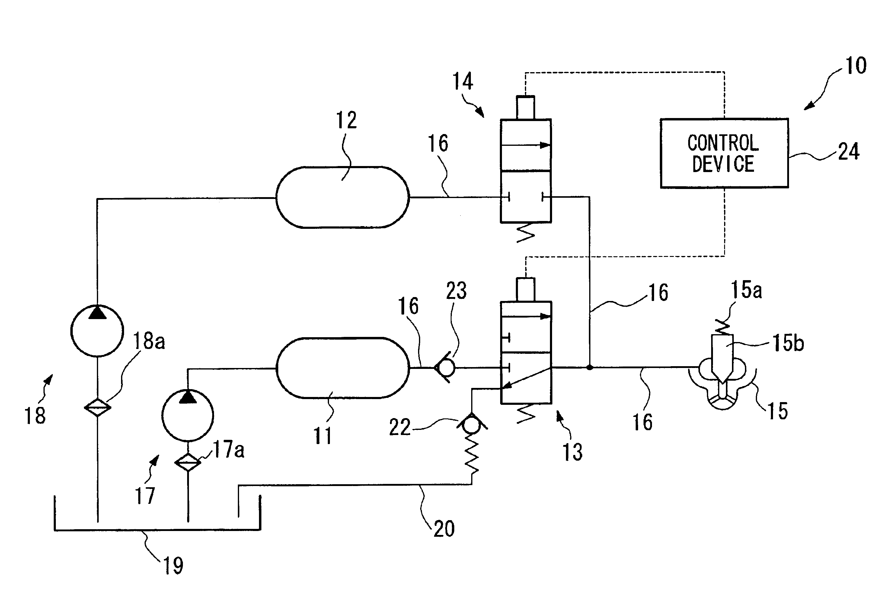
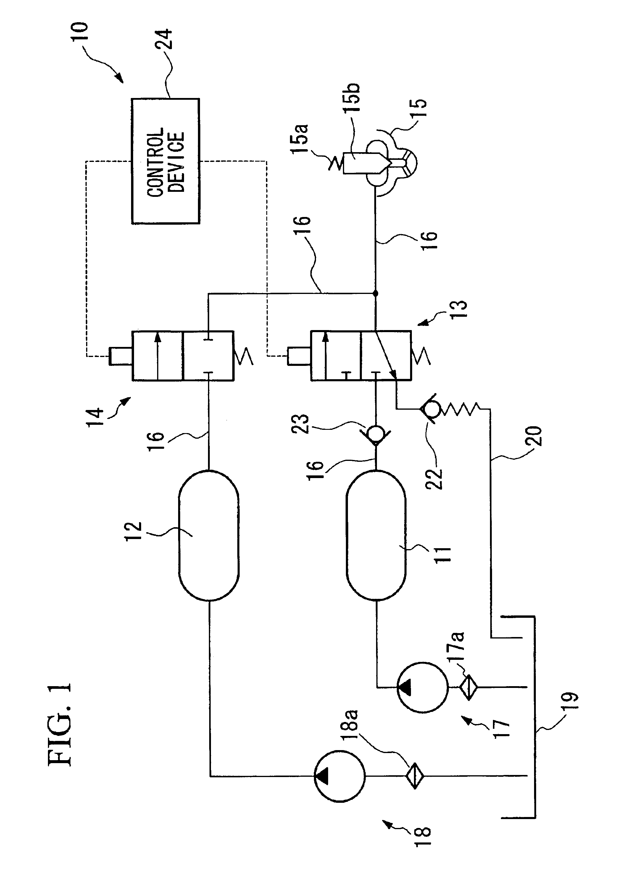
[0069]Below, a first embodiment of the fuel injector according to the present invention and a diesel engine provided with the same will be explained with reference to FIG. 1 to FIG. 4.

[0070]As shown in FIG. 1, the fuel injector 10 has as essential structural elements a low-pressure accumulator (first accumulator) 11, a high-pressure accumulator (second accumulator) 12, a first control valve (first valve mechanism) 13, a second control valve (second valve mechanism) 14, a fuel injection valve 15, a fuel feeding pipe 16, a first pump 17, a second pump 18, and a control device (control means) 24.

[0071]The first accumulator 11 accumulates a fuel, for example, C heavy oil that has been pressurized to, for example, 60 MPa, by the first pump 17.

[0072]The second accumulator 12 accumulates a fuel that has been pressurized to, for example, 160 MPa, by the second pump 18.

[0073]In the figure, reference numerals 17a and 18a denote filters that eliminate impurities from the fuel drawn respectivel...

second embodiment

[0108]The second embodiment of the present invention will be explained with reference to FIG. 7. Moreover, essential components that have already been explained in the first embodiment have identical reference numerals, and their explanation has been omitted.

[0109]The second embodiment shown in FIG. 7 differs significantly from the first embodiment in the point that a three-way selector valve identical to that of the first control valve 13 shown in the first embodiment is used as a second control valve 13′, which is the high-pressure control valve, and the point that the fuel feeding pipe 16 on the outlet side (the fuel injection valve 15 side) of the second control valve 13′ is connected upstream in the direction of the flow of fuel towards the fuel injection valve of the first control valve 13, that is, between the check valve 23 and the first control valve 13.

[0110]Note that in the first embodiment, the fuel feeding pipe 16 on the outlet side of the second control valve 14 is con...

third embodiment

[0115]The third embodiment of the present invention will be explained with reference to FIG. 8 through FIG. 10. Moreover, essential components that have already been explained in the first embodiment have identical reference numerals, and their explanation has been omitted.

[0116]The present embodiment differs significantly from the first embodiment in the point that an inlet throttling valve (a fuel pressure reducing device) is provided as a main structural component.

[0117]In the present embodiment, the first accumulator 11 accumulates fuel pressurized, for example, to 160 MPa by the first pump 17, and the second accumulator 12 accumulates fuel (C heavy oil) pressurized, for example, to 160 MPa by the second pump 18.

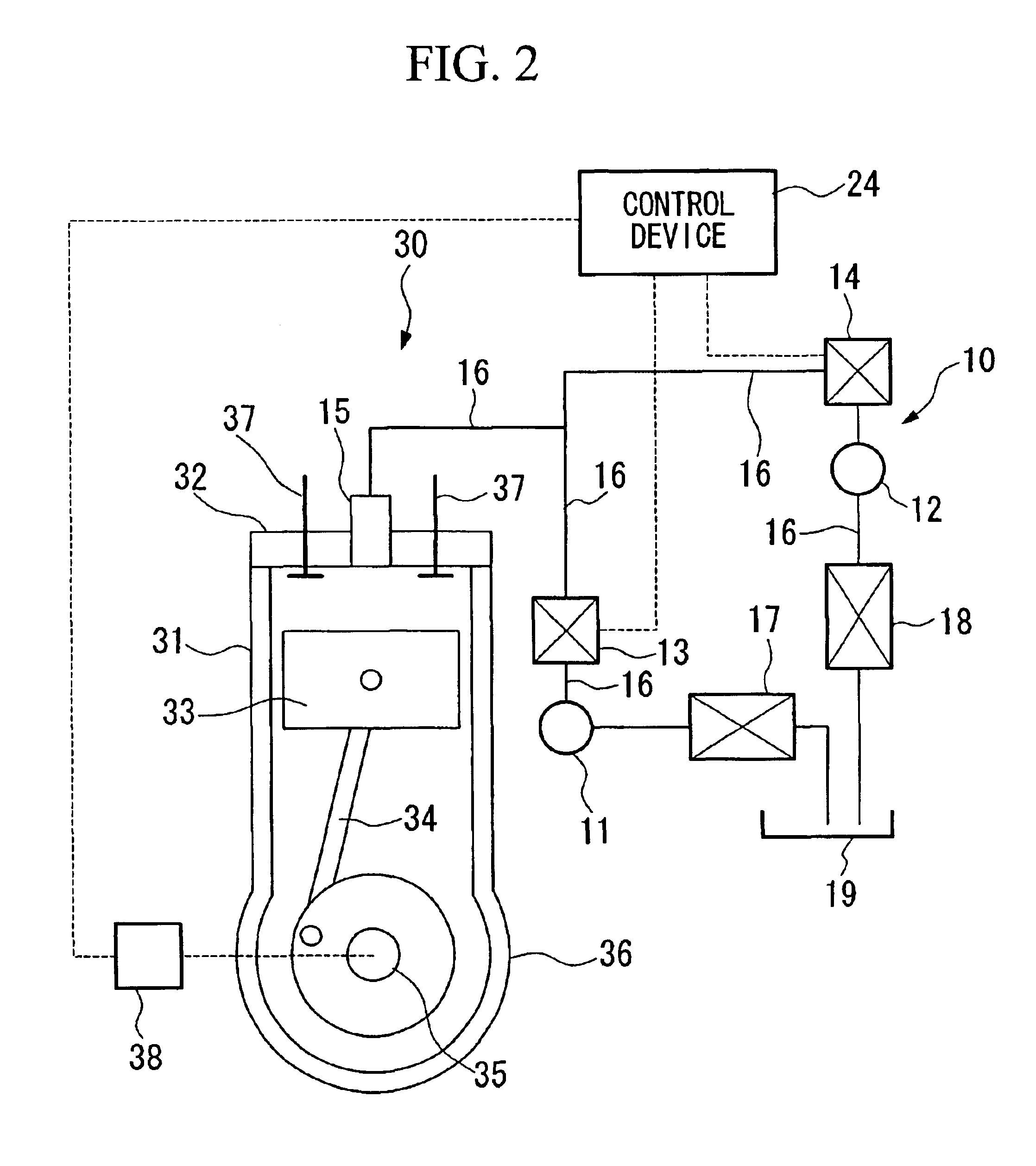
[0118]The reciprocal diesel engine 30 in the present embodiment is shown in FIG. 8.

[0119]As shown in FIG. 8, the inlet throttling valve 25 that characterizes the present embodiment is a flow regulating valve provided upstream of the first pump 17, that is, between the fi...


PUM


Abstract

A fuel injector can reduce the smoke emissions generated during low load and decrease NOx during high load. The fuel injector comprises a first accumulator for accumulating a pressurized fuel, a second accumulator for accumulating a fuel having a higher pressure than the pressure of the fuel in the first accumulator, fuel injection valves to which the fuel from the first and second accumulators is supplied and thereby the fuel injection valves are opened, and the fuel is injected, fuel feeding pipes for feeding the fuel accumulated in the first and second accumulators to the fuel injection valves; a first valve mechanism which is provided at the fuel feeding pipe and which opens and allows the flow of the fuel in the first accumulator to the fuel injection valves, a second valve mechanism which is provided at the fuel feeding pipe and which opens and allows the flow of the fuel in the second accumulator to the fuel injection valves, and a control device for controlling the first and second valve mechanisms. The first accumulator and the first valve mechanism, and the second accumulator and the second valve mechanism, are provided in parallel to each other to the fuel feeding pipe. In a normal injection mode, the control device makes the first and second valve mechanisms open at the same time. In an injection rate control mode, the control device makes an open timing of the first valve mechanism earlier than an open timing in the normal injection mode.

Description

BACKGROUND OF THE INVENTION[0001]1. Field of the Invention[0002]The present invention relates to a fuel injector and to a diesel engine provided with the fuel injector.[0003]2. Description of the Related Art[0004]As an accumulator fuel injector, a fuel injector comprising one accumulator accumulating a pressurized fuel, fuel injection valves to which the fuel is supplied from the accumulator, and thereby the fuel injection valves are opened and the fuel is injected, fuel feeding pipes for feeding the fuel accumulated in the accumulator to the fuel injection valves, and one valve mechanism which is provided to the fuel feeding pipe and which opens and allows the flow of the fuel in the accumulator to the fuel injection valves.[0005]In the fuel injector, regardless of increase and decrease of a load applied to the fuel injector, a fuel injection rate is substantially fixed during fuel injecting. Therefore, in this fuel injector, smoke emission during low load is reduced due to high in...

Claims


Application Information

Patent Timeline
Patent Type & Authority Patents(United States)
IPC IPC(8): F02M63/02F02M63/00F02M45/12F02M45/00
CPCF02M45/00F02M45/12F02M63/0225F02M63/029F02M63/0007F02M2200/40
Inventor NAMEKAWA, SHOJIYOSHIZUMI, HIROSHIISHIDA, HIROYUKI
Owner MITSUBISHI HEAVY IND ENGINE & TURBOCHARGER LTD
Why Eureka
Try Eureka