
Automatic fire-leading igniting device and igniting method for biomass briquette

A technology of briquetting fuel and biomass, which is applied in the combustion method, combustion ignition, incandescent ignition, etc., can solve the problems of unsuitable briquetting fuel, changing electrode discharge characteristics, explosion of molding material, etc., to reduce ignition time and soot emission, Effects of reduced smoke and dust content and reduced ignition energy consumption

Active Publication Date: 2015-01-07
济南长城空调公司
View PDF6 Cites 6 Cited by
  • Summary
  • Abstract
  • Description
  • Claims
  • Application Information

AI Technical Summary

Problems solved by technology

However, the ignition of combustible gases such as propane and butane not only requires storage space, but also may cause explosion and other safety hazards if the molding material is on fire after leakage.
The electric pulse ignition proposed in the invention patent (application number 2014101512789) has the problem of intermittent ignition sparks when the electrode gap is too large, and the success rate of ignition when the electrode gap is small, because the formed pyrolysis gas changes the discharge characteristics of the electrodes
[0005] In addition, for molded fuels with high ash content, the combustible gas is relatively reduced during pyrolysis and the pyrolysis peak time is short, and it is difficult for oxygen to diffuse into the surface layer of the particles.
[0006] Although the ignition device of foreign wood briquette fuel can ignite quickly, it is not suitable for briquette fuel rich in resources such as corn stalks and cotton stalks with high ash content, because the fuel contains a considerable amount of ash, which is easy to produce slagging during combustion
Most ignition devices cannot determine whether the ignition is successful, and it is troublesome to re-ignite after ignition failure, and it is impossible to realize the automation of direct combustion equipment

Method used


Image

  • Automatic fire-leading igniting device and igniting method for biomass briquette
  • Automatic fire-leading igniting device and igniting method for biomass briquette
  • Automatic fire-leading igniting device and igniting method for biomass briquette

Examples


Embodiment Construction

[0036] The present invention will be further described in detail below in conjunction with the accompanying drawings and preferred embodiments.

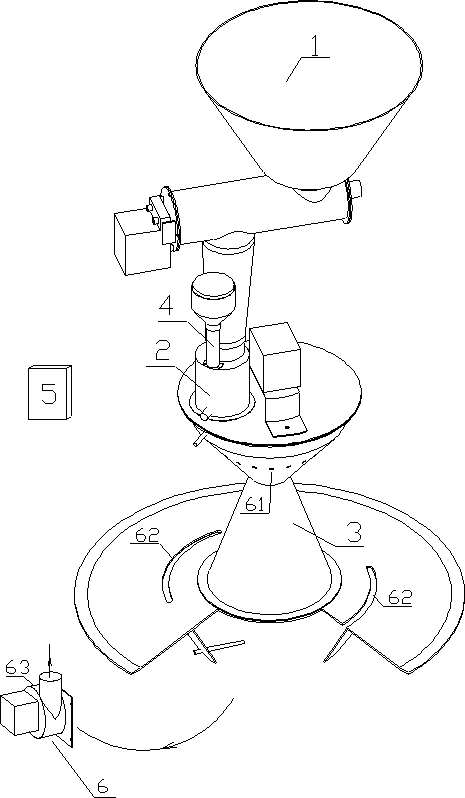
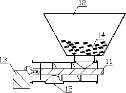
[0037] see Figure 1-Figure 4 , the present invention includes a feeding device 1, an ignition chamber 2, a main combustion device 3, an ignition device 4, a control device 5, and a smoke exhaust device 6, the feeding device 1 is located above the ignition chamber 2, and the ignition chamber 2 is located at the main combustion device 3 Above, the ignition device 4 is located above the ignition chamber 2.

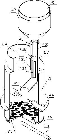
[0038]The ignition device 4 includes a DC motor 41, a blower fan 42, an electric heating device 43, a high-voltage discharge needle 44, an ignition tube 22 and a hot air outlet 45, and the electric heating device 43 is located in the ignition tube 22, and the ignition tube 22 Located above the ignition chamber 2 , the air outlet velocity range of the ignition tube 22 is 1.9-2.3m / s, and the high-voltage discharge needle 44 is locat...


PUM


Abstract

The invention discloses an automatic fire-leading igniting device and an igniting method for biomass briquette. The automatic fire-leading igniting device comprises an ignition chamber, and is characterized in that a feeding device and an ignition device are arranged above the ignition chamber, a main combustion device is disposed below the ignition chamber, and a smoke discharge device is mounted on one side of the main combustion device. According to the automatic fire-leading igniting device and the igniting method for the biomass briquette, ignition of the biomass briquette is divided into ignition of leading fire and ignition of main fire, a fire-leading material is ignited and then a main material is ignited, forming materials are few during ignition of leading fire, the passing air amount is small, reliably rapid ignition can be achieved, ignition energy consumption is reduced, and smoke discharge amount and dust content are reduced.

Description

technical field [0001] The invention relates to the field of biomass briquette fuel combustion, in particular to an automatic ignition device and ignition method for biomass briquette fuel. Background technique [0002] With the acceleration of urbanization and the continuous improvement of farmers' living standards, rural energy consumption continues to expand, and the contradiction between rural energy supply and demand has become increasingly acute. Biomass with "recyclability" and "environmental protection" will become the main heating element for new rural buildings. One of energy. At present, biomass briquettes are mainly used for biomass power generation, building heating, and cooking, and the utilization method is mainly direct combustion, especially for household heating in Europe, Canada and other countries. [0003] Ignition in direct combustion is the key. Biomass ignition mostly adopts technical methods such as hot air ignition, solid or liquid fuel igniti...

Claims


Application Information

Patent Timeline
IPC IPC(8): F23Q7/02
Inventor 张林华崔永章曲云霞高贵凤唐明天
Owner 济南长城空调公司
Learn More