Aircraft engine pod with acoustic attenuation

a technology of aircraft engine and acoustic attenuation, which is applied in the direction of combustion air/fuel air treatment, air flow influencers, instruments, etc., to achieve the effect of eliminating almost completely the noise emitted by the engine fan and increasing the attenuation performan

Inactive Publication Date: 2005-05-24
AIRBUS OPERATIONS (SAS)
View PDF24 Cites 43 Cited by
  • Summary
  • Abstract
  • Description
  • Claims
  • Application Information

AI Technical Summary

Benefits of technology

[0009]The purpose of the present invention is to overcome this drawback, to increase the attenuation performance of said internal piece of the air intake and to eliminate almost completely the noise emitted by the engine fan.

Problems solved by technology

Thus, said tubular transition part, which is indispensable but which represents only a very small part of the surface of the internal duct of the pod, is in actual fact the cause of the limitation on the performance of the acoustic attenuation internal piece of the air intake and this, hitherto, has escaped the attention of the person skilled in the art precisely because of the insignificant size of said tubular transition part.

Method used


Image

  • Aircraft engine pod with acoustic attenuation
  • Aircraft engine pod with acoustic attenuation
  • Aircraft engine pod with acoustic attenuation

Examples


Embodiment Construction

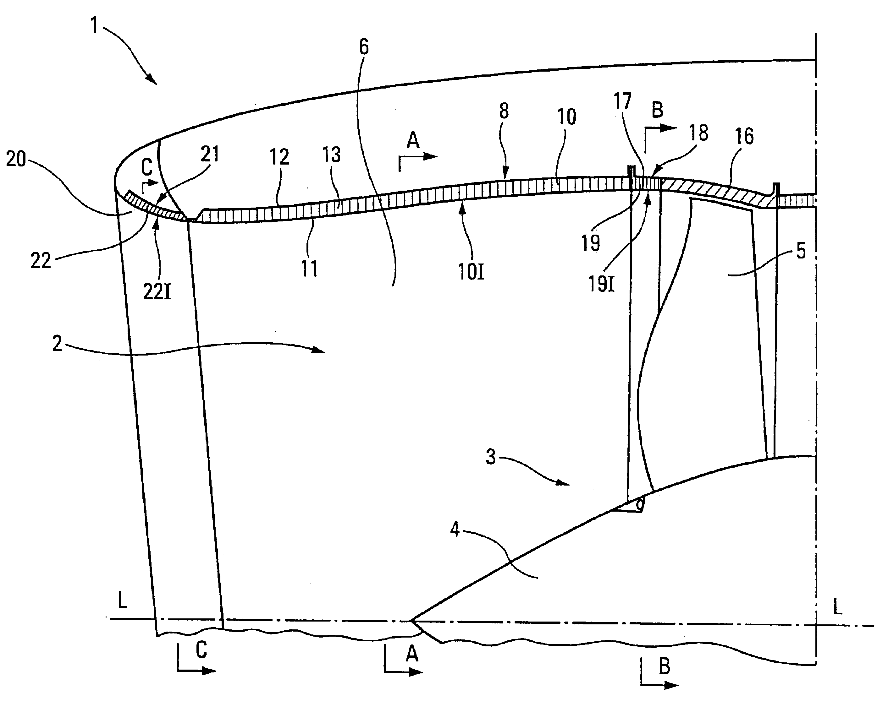
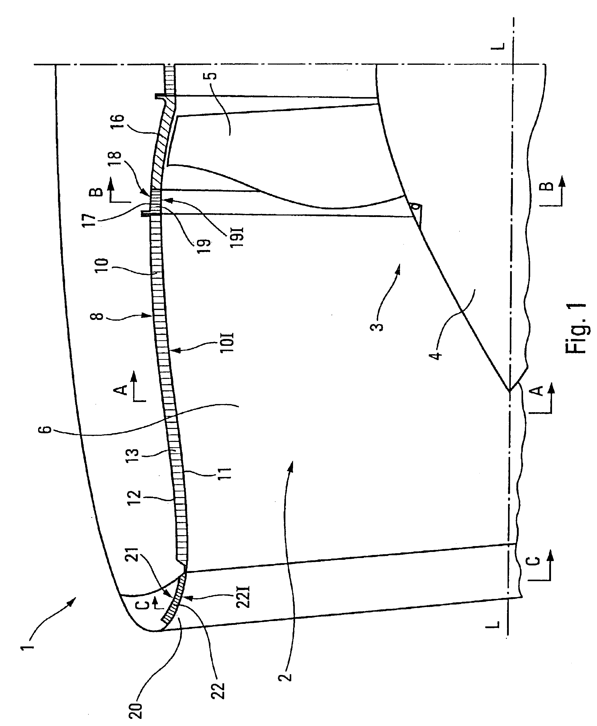
[0033]The front part of the engine pod 1 according to the present invention, depicted in part and schematically in FIG. 1, defines an internal duct 2 inside which a fan 3 is arranged. The fan 3 comprises a rotary hub 4 of axis L—L, provided with blades 5.

[0034]Forward of the blades 5, the internal duct 2 forms a tubular air intake 6.

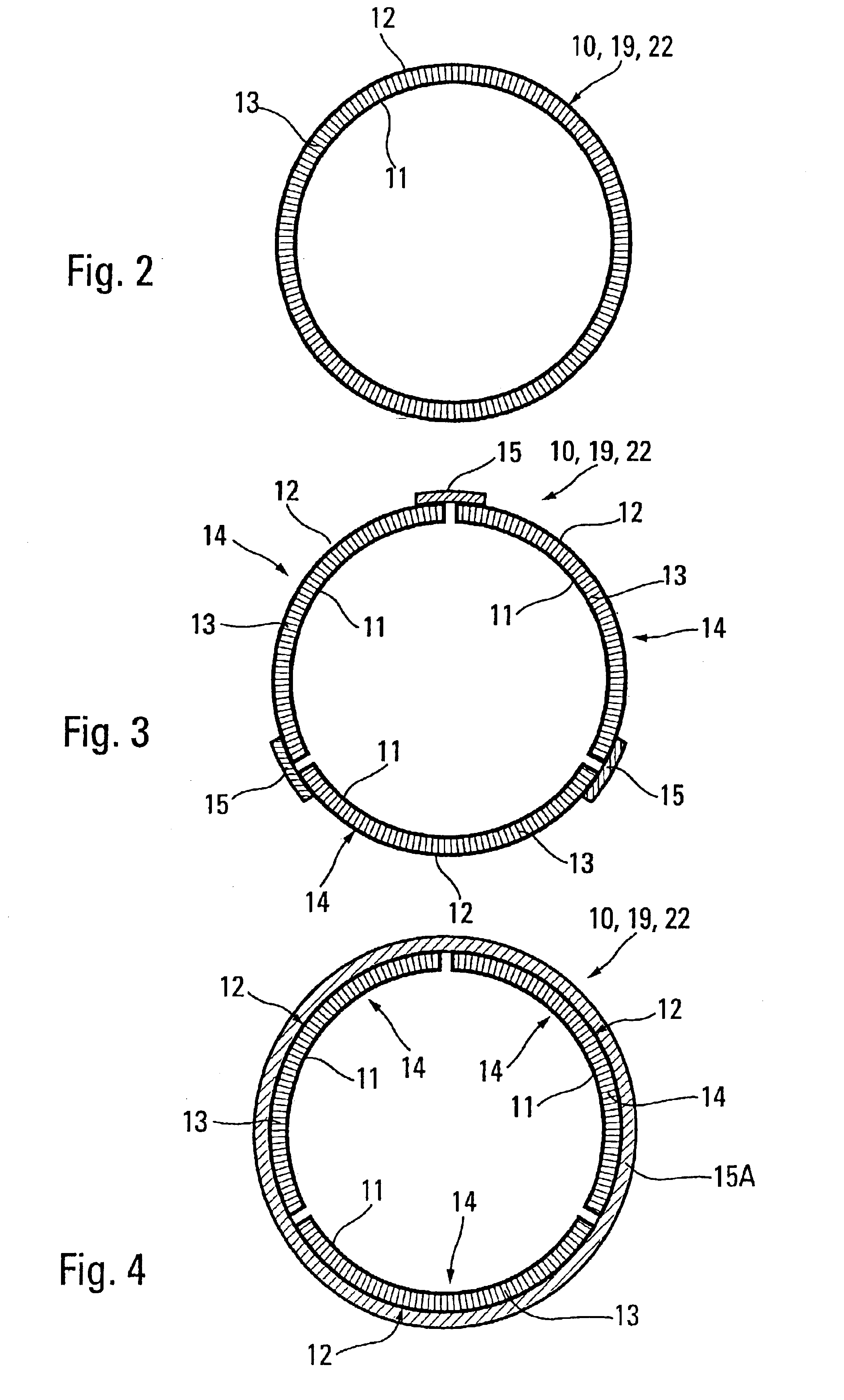
[0035]In a known way, the wall 8 of the air intake 6 is formed of an acoustic attenuation tubular piece 10 comprising a permeable internal skin 11, an impermeable external skin 12 and a cellular core 13 inserted between said internal and external skins 11 and 12. The acoustic attenuation piece 10 may, for example, be produced in a single piece (see FIG. 2) or as several longitudinal shells 14 assembled by external fishplate strips 15 (see FIG. 3) or by an external annulus 15A (see FIG. 4). Whatever its embodiment, the acoustic attenuation piece 10 has no assembly fishplate on its internal face 10I, consisting of the internal skin 11.

[0036]Facing the blad...


PUM


Abstract

An internal duct of an aircraft engine pod may include a fan and a tubular air intake having a first acoustic attenuation internal tubular piece. The first acoustic attenuation internal tubular piece is acoustically homogeneous, is of the resonator type, and has no internal assembly fish-plate. Additionally, the internal duct may include a tubular fan casing and a tubular transition part for connecting the air intake to the fan casing. An internal face of the tubular transition part is acoustically homogeneous also. Moreover, the internal face of the first acoustic attenuation internal tubular piece and the internal face of the tubular transition part are disposed in aerodynamic continuity.

Description

BACKGROUND OF THE INVENTION[0001]The present invention relates to an aircraft engine pod with optimized acoustic attenuation.[0002]It is known that the engines fitted to aircraft are sources of noise at a very high level. This is particularly troublesome when the aircraft equipped with these engines is located near to an inhabited area, for example during takeoff or landing. Environmental standards, which are becoming increasingly strict, dictate that the noise level of an aircraft, and therefore the noise level of the engines, be kept below a legislatory threshold so as to limit the noise nuisance suffered by the inhabitants of said area. This legislatory threshold is sometimes reduced further during the night, which means that the noisiest aircraft can then neither land nor take off, which is a constraint, or even a loss of potential income, for the airlines which operate such aircraft. In consequence, it is desirable to reduce the level of acoustic emissions of such an engine to ...

Claims


Application Information

Patent Timeline
Patent Type & Authority Patents(United States)
IPC IPC(8): F02C7/045F02C7/04
CPCB64D33/02F02C7/045B64D2033/0206Y02T50/672B64D2033/0286Y02T50/60
Inventor PORTE, ALAINBATARD, HERVE
Owner AIRBUS OPERATIONS (SAS)
Why Eureka
Try Eureka