Scroll compressor with hot oil temperature responsive relief of back pressure chamber

a compressor and back pressure technology, applied in the direction of machines/engines, rotary/oscillating piston pump components, liquid fuel engines, etc., can solve the problems of damage along the contact surface, affecting the operation, and a large amount of inter-fitting contact surfaces

Inactive Publication Date: 2005-05-24
SCROLL TECH
View PDF6 Cites 31 Cited by
  • Summary
  • Abstract
  • Description
  • Claims
  • Application Information

AI Technical Summary

Benefits of technology

[0009]Preferably, that same oil also drips onto the motor protector. In addition, by opening the back pressure chamber, the scroll members will be allowed to move away from each other, and will more readily resist the problems with galling, undue tip thrust, etc. mentioned above.

Problems solved by technology

Various operational challenges exist with the scroll compressor.
In particular, the complex surfaces between the two scroll members present a good deal of interfitting contact surfaces.
Under certain conditions, there can be damage along the contact surfaces.
This will cause unduly high temperatures to quickly exist in the scroll compressor.
This can lead to various damage to the compressor components.
Further, another problem can exist due to the cooling method utilized in most sealed compressors.
However, under certain conditions, the charge of refrigerant in the system may be unduly low.
When there is a low amount of suction refrigerant moving over the motor, the motor may not be adequately cooled.
To date, the known scroll compressors have not adequately provided more prompt relief of the adverse conditions.

Method used


Image

  • Scroll compressor with hot oil temperature responsive relief of back pressure chamber
  • Scroll compressor with hot oil temperature responsive relief of back pressure chamber
  • Scroll compressor with hot oil temperature responsive relief of back pressure chamber

Examples


Embodiment Construction

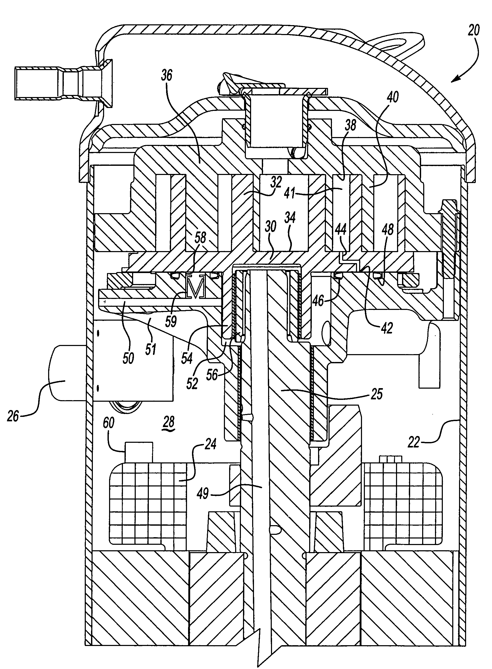
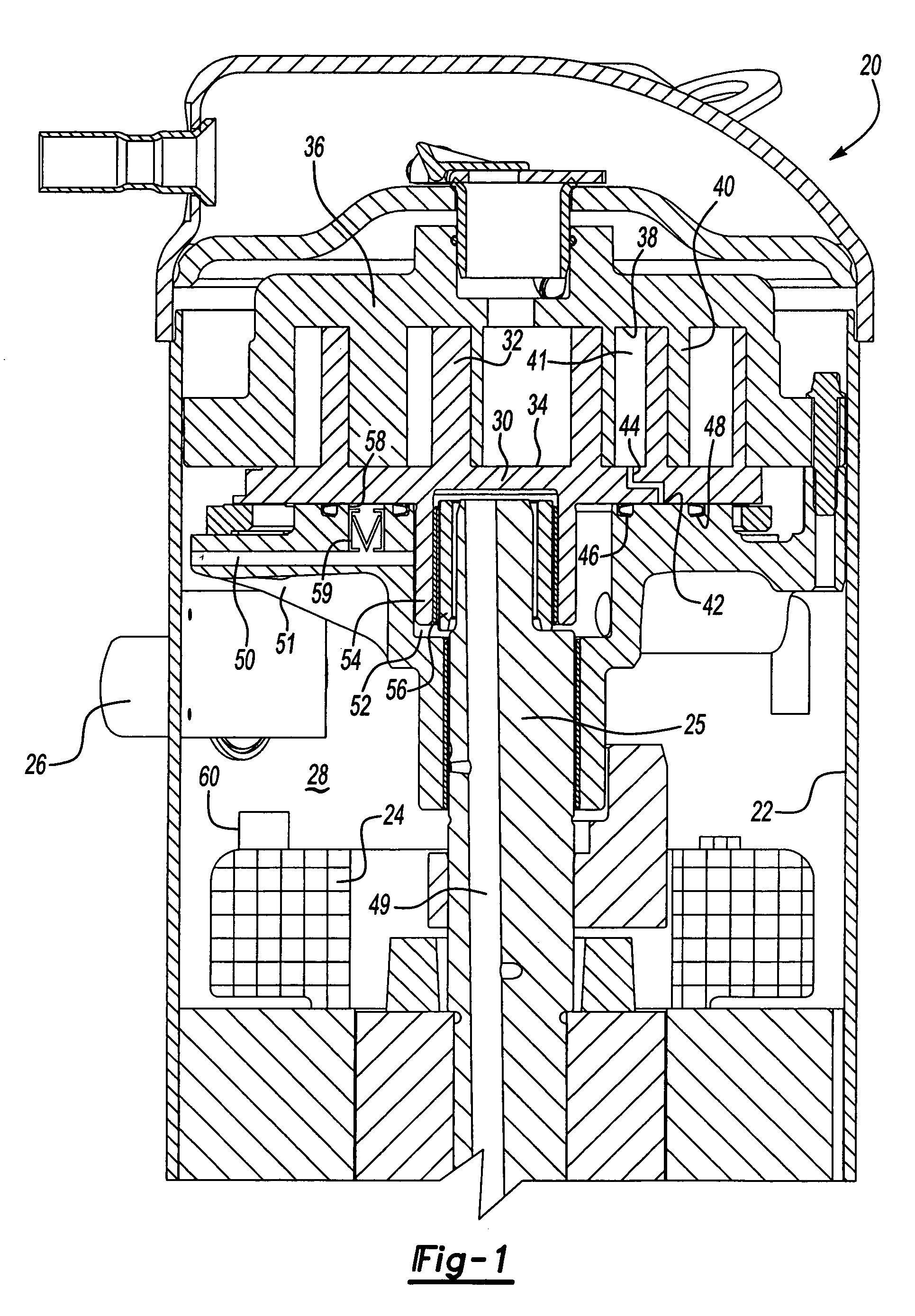
[0014]A scroll compressor 20 is illustrated in FIG. 1. Scroll compressor 20 is housed within a sealed housing 22. As known, an electric motor 24 drives a shaft 25 to compress a refrigerant. The refrigerant enters the sealed housing 22 through a suction tube 26. A suction chamber 28 surrounds the motor, and a suction refrigerant can pass over the motor to cool the motor.

[0015]A first scroll member 30, known as an orbiting scroll, includes a spiral wrap 32 extending from a base 34. The illustrated scroll wrap is of a so-called “hybrid” style having varying thickness in its scroll wraps. Other types of scroll compressors would come within the scope of this invention, including a scroll wrap formed on an involute of a circle, which would have a relatively constant thickness to its wraps. The orbiting scroll 30 faces a non-orbiting scroll 36 having a base 38 in its own wrap 40 extending from the base. As shown, the wraps interfit to define compression chambers 41. The drive shaft 25 is d...


PUM


Abstract

A scroll compressor includes a protection device that has a valve movable between a position blocking flow from the back pressure chamber into the suction chamber, and a position allowing such flow. The valve is movable dependent on an oil temperature. Under adverse conditions, the oil will reach higher temperatures and the valve will open allowing flow of refrigerant from the back pressure chamber into the suction chamber. This refrigerant will likely be at an elevated temperature, and will assist the heated oil in moving a motor protection switch associated with the motor to shut down the motor. Moreover, by relieving the back pressure chamber, the two scroll members are allowed to move out of contact with each other, thereby reducing potential damage due to the adverse conditions.

Description

BACKGROUND OF THE INVENTION[0001]This application relates to a scroll compressor having a protection device that releases the back pressure chamber refrigerant if an oil temperature reaches an undesirably high level. The present invention thus better addresses certain operational problems more quickly than the prior art.[0002]Scroll compressors are becoming widely utilized in refrigerant compression applications. In a scroll compressor, a pair of scroll members each include a base and a generally spiral wrap extending from the bases. The wraps interfit to define compression chambers. One of the two scroll members is caused to orbit relative to the other, and as the two orbit, the size of the compression chambers is reduced, compressing an entrapped refrigerant. As the refrigerant pressure increases, a separating force from the refrigerant tends to force the two scroll members away from each other. Thus, scroll compressor designers tap a portion of a compressed refrigerant to a chamb...

Claims


Application Information

Patent Timeline
Patent Type & Authority Patents(United States)
IPC IPC(8): F01C1/00F01C1/02F04C18/02F04C18/00F04C29/04F04C28/26F04C28/28
CPCF04C18/0215F04C28/28F04C28/265F04C2270/19
Inventor PATEL, TAPESH P.
Owner SCROLL TECH
Why Eureka
Try Eureka