Abrasive blasting apparatus

a blasting apparatus and abrasive technology, applied in the direction of abrasive equipment, blast generating devices, abrasive machine components, etc., can solve the problems of reducing the blasting effect, and consuming a large quantity of water or other blasting liquid during the blasting operation, so as to increase the quantity of particulate blasting medium

Inactive Publication Date: 2005-05-24
QUILL INTERNATIONAL INDUSTRIES PLC
View PDF15 Cites 7 Cited by
  • Summary
  • Abstract
  • Description
  • Claims
  • Application Information

AI Technical Summary

Benefits of technology

[0014]According to the present invention there is provided a blasting apparatus comprising a blasting apparatus comprising a pressure vessel adapted to contain a particulate blasting medium and a liquid and including an inlet and a bottom outlet; a conduit along which an entraining pressurized gas can be fed from a pressurizing gas source and with which the interior of the vessel communicates via an opening in the conduit connected to the outlet, the flow of pressurized fluid through the conduit entraining the contents of the vessel for dispersal into the fluid flow for blasting through a delivery line connected to the conduit; a pressurizing means to pump liquid from a liquid source into the vessel behind its contents in terms of its contents' outflow from the vessel through the bottom outlet; valve means to control the flow of pressurized gas along the conduit; and characterised in that a venturi is located in the conduit immediately upstream of the opening connected to the bottom outlet of the vessel so that the velocity of the pressurized gas is increased as it passes over the opening thereby to increase the quantity of particulate blasting medium entrained by the gas.
[0021]Preferably, the wall of the lower portion of the vessel defines a shallow dish to encourage flow of the particulate material through the bottom outlet.

Problems solved by technology

Such an arrangement, however, requires a separate pump to be used to deliver the liquid into the abrasive and gaseous stream, which makes the cost of the blasting apparatus more expensive than is desirable and renders the blasting apparatus more prone to breakdown.
However, the aforementioned apparatus all suffer from the disadvantage that a considerable quantity of water or other blasting liquid is used during a blasting operation.
This makes the operation messy as large quantities of liquid must be disposed of and the object of the cleaning operation is thoroughly wetted, which can be disadvantageous.
However, this apparatus also suffers from the disadvantage that the entrained abrasive particles tend not to be evenly dispersed within the pressurized blasting fluid but clumped together in groups or pockets so that the resulting jet of blasting fluid is not uniform in nature.

Method used


Image

  • Abrasive blasting apparatus
  • Abrasive blasting apparatus
  • Abrasive blasting apparatus

Examples


Embodiment Construction

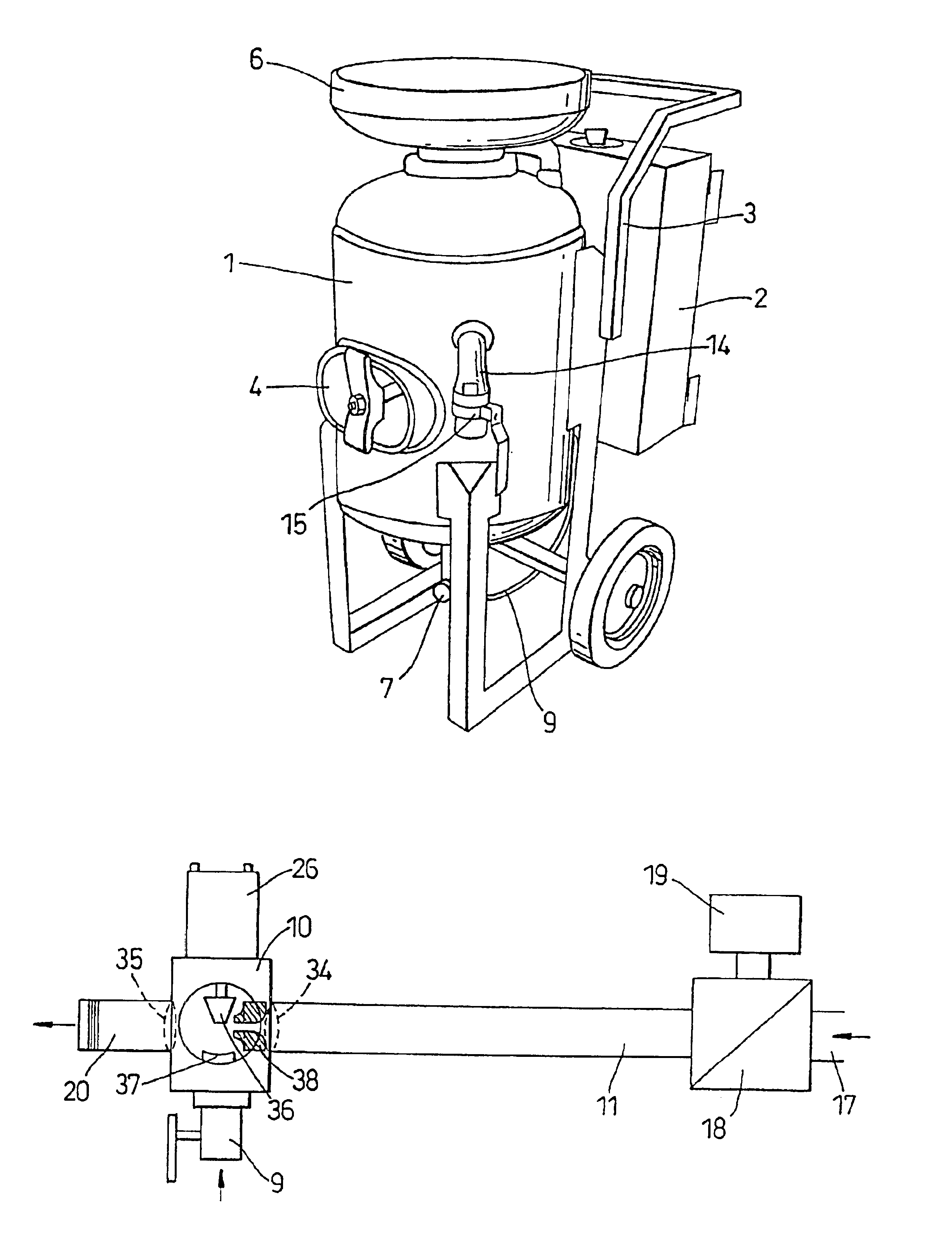
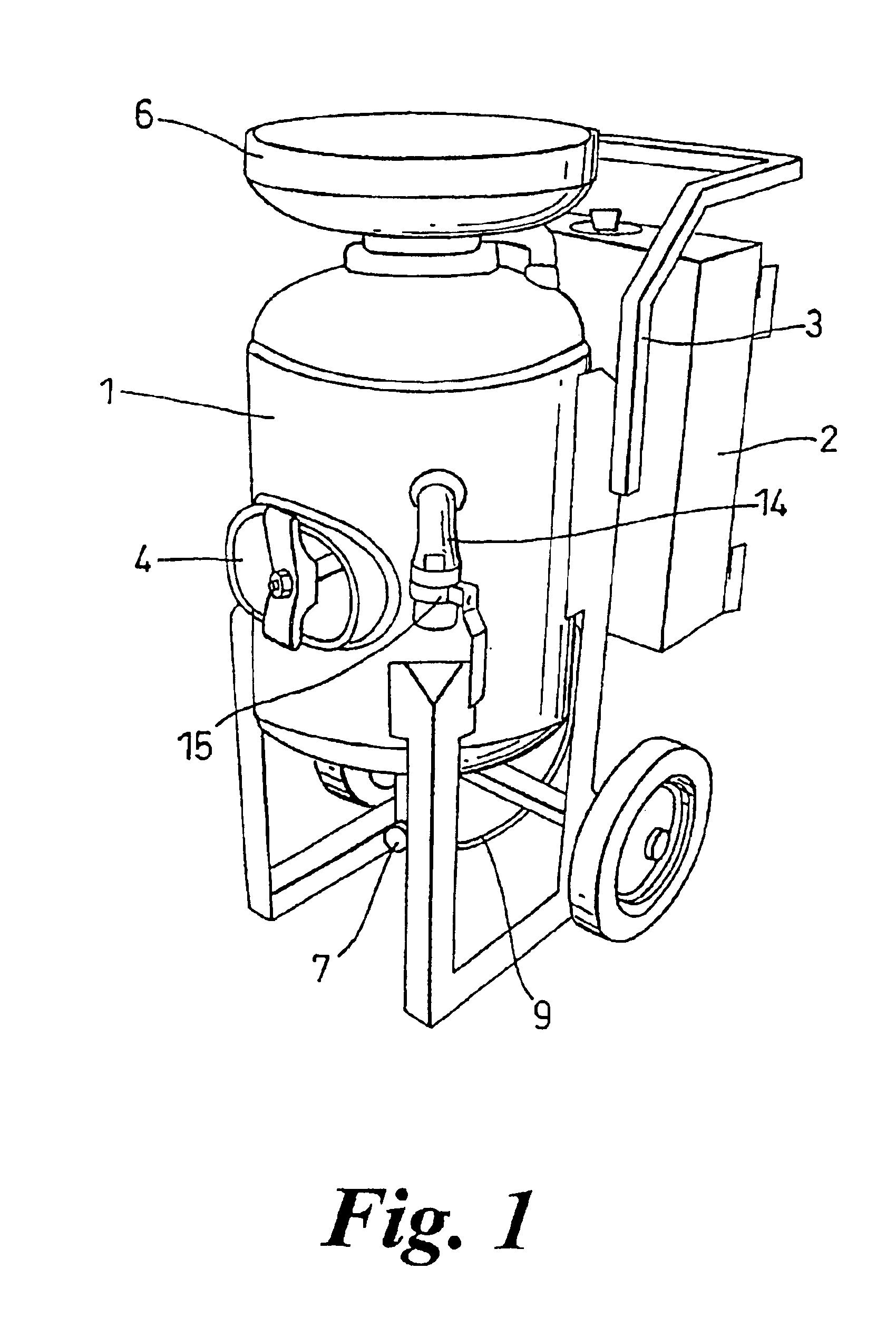
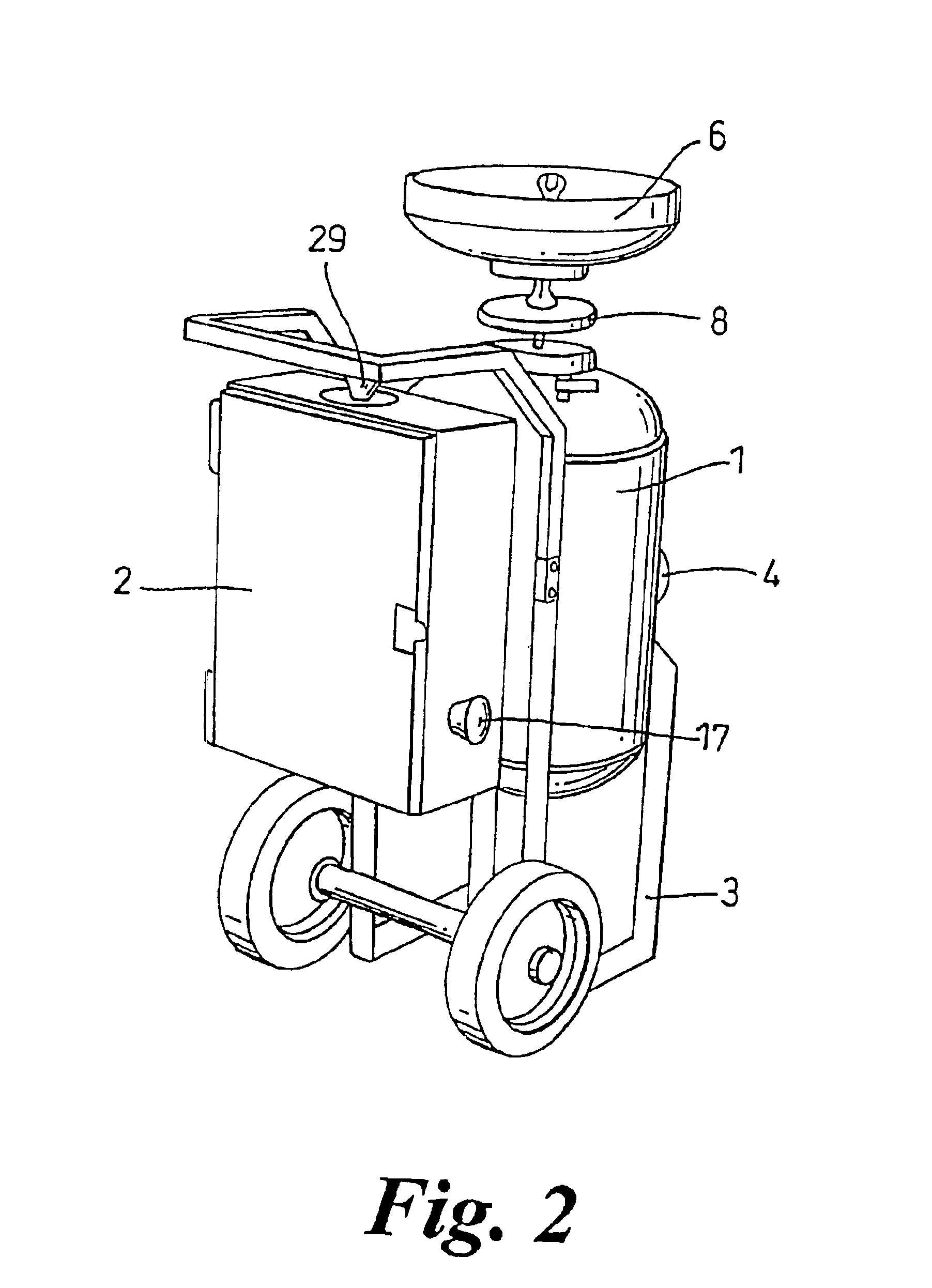
[0030]An apparatus according to the invention comprises a pressure vessel 1 to one side of which is attached a control box 2. Preferably, both the vessel 1 and the control box 2 are mounted on framework forming a wheeled trolley 3 with a handle to enable the apparatus to be wheeled close to an object to be blasted.

[0031]The pressure vessel 1 is adapted to contain a blasting mixture of a particulate material and a liquid, which is typically water or a water based blasting solution as aforesaid. The vessel 1 is provided with a side inspection plate 4, which during operation of the apparatus is kept shut, and a top blasting medium inlet 5. The inlet 5 is defined centrally at the base of a detachable sieve 6 located at the top of the vessel 1. The vessel also has a bottom outlet 7, which is disposed at a central portion of the bottom of the vessel 1. The inlet 5 can be closed by a seal 8, which is located beneath the sieve 6, in order that the vessel 1 can be internally pressurized. The...


PUM


Abstract

A blasting apparatus includes a pressure vessel adapted to contain a particulate blasting medium and a liquid. The vessel includes an inlet and a bottom outlet. The interior of the vessel communicates via its bottom outlet with an opening in a conduit along which conduit an entraining pressurized gas can be fed from a pressurizing gas source. A pressurizing device is provided to pump liquid from a liquid source into the vessel behind its contents in terms of its contents' outflow from the vessel through the bottom outlet. A valve is provided to control the flow of pressurized gas along the conduit. Immediately upstream of the opening in the conduit is located a venturi so that the velocity of the pressurized gas is increased as it passes over the opening thereby increasing the quantity of particulate blasting medium entrained by the gas.

Description

RELATED U.S. APPLICATIONS[0001]Not applicable.STATEMENT REGARDING FEDERALLY SPONSORED RESEARCH OR DEVELOPMENT[0002]Not applicable.REFERENCE TO MICROFICHE APPENDIX[0003]Not applicable.FIELD OF THE INVENTION[0004]The present invention relates to an abrasive blasting apparatus and in particular to a dustless abrasive blasting apparatus.BACKGROUND OF THE INVENTION[0005]In dustless abrasive blasting, an abrasive is entrained in a pressurized liquid flow or gaseous-entrained liquid flow and is directed against the surface to be treated by a controllable nozzle. It is the intention of such apparatus to coat each particle of the abrasive with the liquid so that the abrasive is weighted by the liquid and falls safely to the ground after striking the surface to be blasted, generally obviating the requirement for the operator of the apparatus to wear breathing apparatus. The weighted abrasive also increases the efficiency of the blasting operation.[0006]Typically, the liquid used in abrasive b...

Claims


Application Information

Patent Timeline
Patent Type & Authority Patents(United States)
IPC IPC(8): B24C7/00
CPCB24C7/0038
Inventor DORE, DAVID JAMES
Owner QUILL INTERNATIONAL INDUSTRIES PLC
Why Eureka
Try Eureka