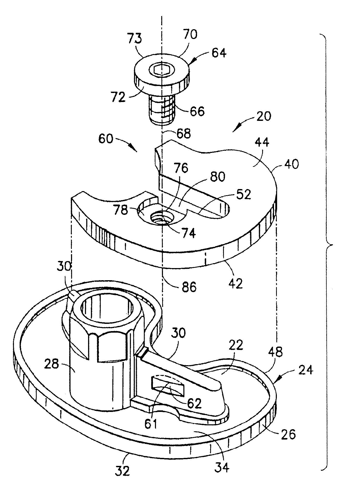
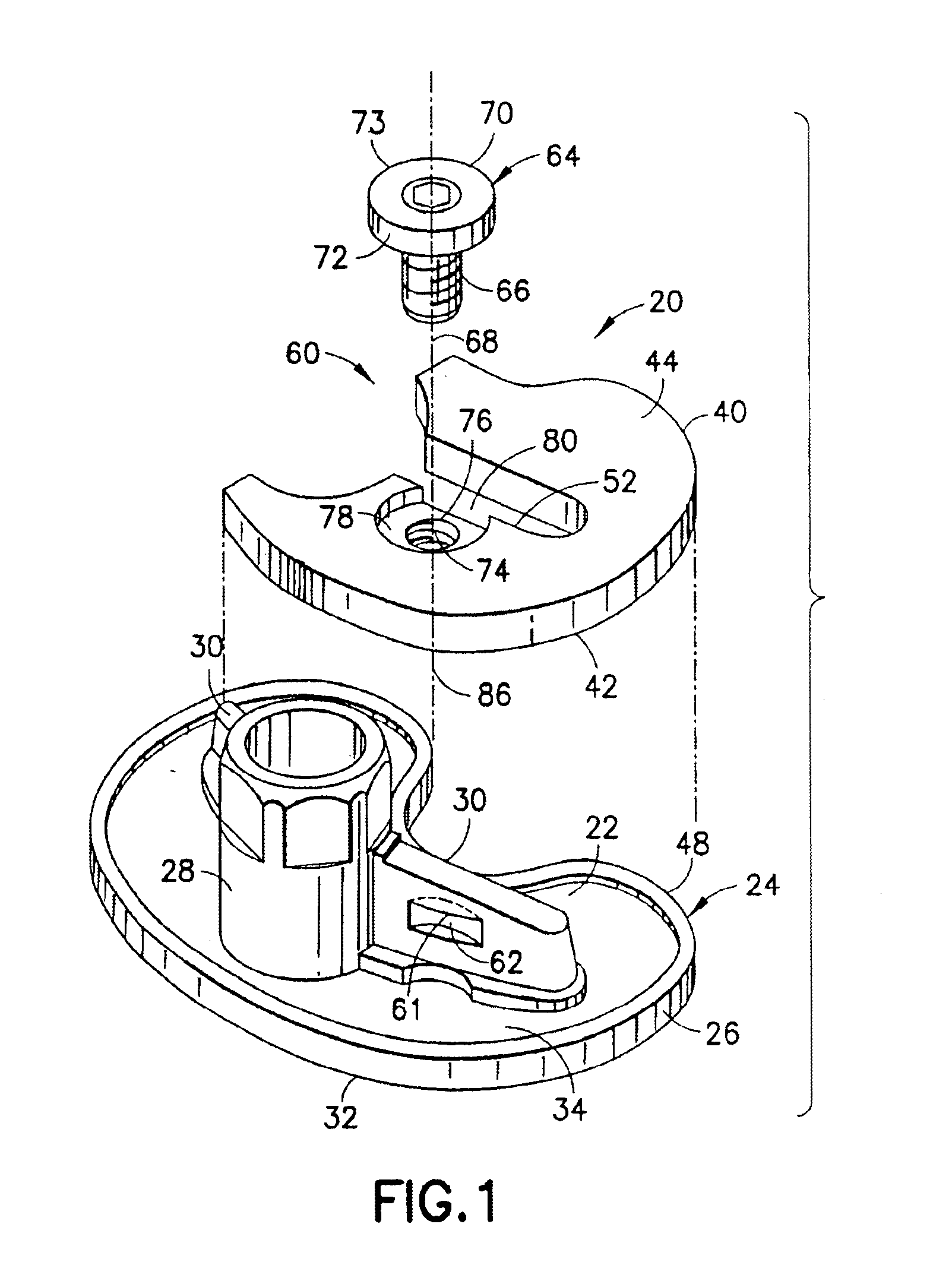
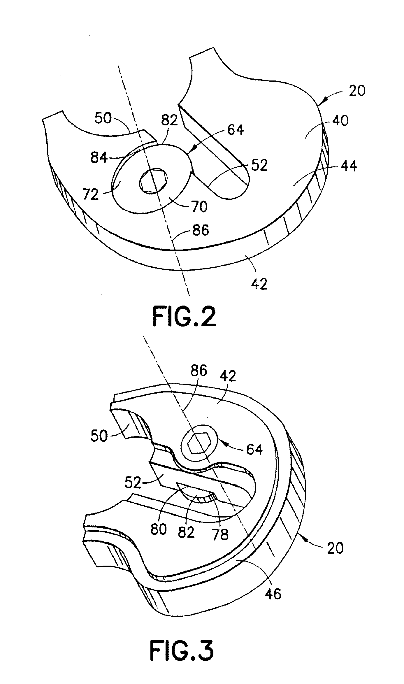
[0007]The present improvement provides a construction and method which facilitates the securement of a selected augment to an implant component, such as the securement of a selected tibial augment to a tibial implant component, while avoiding the drawbacks outlined above. As such, the present improvement attains several objects and advantages, some of which are summarized as follows: Enables a, surgeon quickly and effectively to attach a selected augment to an implant component, such as the attachment of a selected tibial augment to a tibial implant component, interoperatively, without resorting to cementing and clamping, as described above, and without the necessity for assembling loose fasteners with the augment and the implant component; avoids deleterious effects which otherwise could result from migrating particulate
polyethylene, as described above, as well as cold flow of polyethylene due to excessive stress at surfaces where the bearing member of a tibial implant is supported by the tibial tray of a tibial implant component; provides a self-contained augment in which a securement mechanism is assembled in the factory as a part of the augment for ready use by a surgeon without the necessity for further
assembly of augment component parts during the implant procedure; simplifies the selection and placement of an appropriate augment at an implant site without undue
delay, thereby benefitting the recipient of a prosthetic implant, as well as assisting the surgeon; provides a simple and highly effective securement arrangement for securing an augment, such as a tibial augment to a tibial implant component without the necessity for special instruments, tools or unusual skills; promotes accuracy and effectiveness in completing a prosthetic implant procedure; enhances the performance and
longevity of a
prosthetic knee implant which requires the use of a tibial augment; provides a relatively rugged implant
assembly capable of exemplary performance over an extended service life.
[0008]The above objects and advantages, as well as further objects and advantages, are attained by the present invention which may be described briefly as an improvement for facilitating securement of a selected tibial augment at an augmentation location on a tibial implant component, the tibial implant component having a tibial tray adjacent the augmentation location and a depending structure extending longitudinally from the tibial tray, the tibial tray having a proximal surface and an opposite distal surface, the improvement comprising: an
abutment on the depending structure, the
abutment extending transversely along the depending structure adjacent the augmentation location; a securing element coupled with the tibial augment for selective rotation about a longitudinal axis of rotation located adjacent the abutment when the tibial augment is placed at the augmentation location and juxtaposed with the tibial tray; and a securing surface on the securing element arranged for longitudinal displacement relative to the abutment upon rotation of the securing element, the longitudinal displacement engaging the securing surface with the abutment to establish a longitudinal securing force between the securing element and the depending structure for urging the tibial augment against the tibial implant component, and thereby secure the tibial augment to the tibial implant component at the augmentation location.
[0009]In addition, the present invention includes a method for facilitating selective securement of a tibial augment at an augmentation location on a tibial implant component, the tibial implant component having a tibial tray adjacent the augmentation location and a depending structure extending longitudinally from the tibial tray, the tibial tray having a proximal surface and an opposite distal surface, the method comprising: providing an abutment on the depending structure, the abutment extending transversely along the depending structure adjacent the augmentation location;
coupling a securing element with the tibial augment for selective rotation about a longitudinal axis of rotation located adjacent the abutment when the tibial augment is placed at the augmentation location and juxtaposed with the tibial tray; providing a securing surface on the securing element; and rotating the securing element to displace the securing surface longitudinally relative to the abutment, the longitudinal displacement engaging the securing surface with the abutment to establish a longitudinal securing force between the securing element and the depending structure for urging the tibial augment against the tibial implant component, and thereby secure the tibial augment to the tibial implant component at the augmentation location.
[0010]Further, the present invention includes an improvement for facilitating securement of a selected augment at an augmentation location on a prosthetic implant component, the improvement comprising: an augment body; an abutment on one of the augment body and the prosthetic implant component, the abutment extending in a first direction along the one of the augment body and the prosthetic implant component, adjacent the augmentation location; a securing element coupled with the other of the augment body and the prosthetic implant component for selective rotation about an axis of rotation extending in a second direction transverse to the first direction and located adjacent the abutment when the augment is placed at the augmentation location and juxtaposed with the prosthetic implant component; and a securing surface on the securing element arranged for displacement in the second direction, relative to the augment body, upon rotation of the securing element about the axis of rotation, the displacement engaging the securing surface with the abutment to establish a securing force in the second direction, between the securing element and the abutment for urging the augment against the prosthetic implant component, and thereby secure the augment to the prosthetic implant component at the augmentation location.
[0011]Still further, the present invention includes a method for facilitating securement of a selected augment at an augmentation location on a prosthetic implant component, the method comprising: providing an abutment on one of the augment and the prosthetic implant component, the abutment extending in a first direction along the one of the augment and the prosthetic implant component, adjacent the augmentation location;
coupling a securing element with the other of the augment and the prosthetic implant component for selective rotation about an axis of rotation extending in a second direction transverse to the first direction and located adjacent the abutment when the augment is placed at the augmentation location and juxtaposed with the prosthetic implant component; and rotating a securing surface on the securing element to displace the securing surface in the second direction, relative to the augment, upon rotation of the securing element about the axis of rotation, the displacement engaging the securing surface with the abutment to establish a securing force in the second direction, between the securing element and the abutment for urging the augment against the prosthetic implant component, and thereby secure the augment to the prosthetic implant component at the augmentation location.


