Stator for a vehicular rotary electric machine and a manufacturing method thereof

a technology of rotary electric machines and stators, which is applied in the direction of manufacturing stators/rotor bodies, magnetic circuit rotating parts, and shape/form/construction of magnetic circuits, etc., can solve the problems of inability to meet the requirements of the adjacent electrical conductor, and achieve the effect of ensuring sufficient clearance and small radial thickness

Inactive Publication Date: 2005-05-24
DENSO CORP
View PDF12 Cites 46 Cited by
  • Summary
  • Abstract
  • Description
  • Claims
  • Application Information

AI Technical Summary

Benefits of technology

[0011]In view of the problems encountered in the prior designs, it is an object of the present invention to provide a stator for a vehicular rotary electric machine and its manufacturing method, in which sufficient clearances are provided in intersecting portions of electrical conductors at one coil end so as to ensure electrical insulation and to improve the cooling efficiency at the coil end.

Problems solved by technology

The end portion of the first electrical conductor which will be bonded to the second, adjacent electrical conductor is susceptible to insulation film troubles such as peeling and cracking because of the heat of welding.

Method used


Image

  • Stator for a vehicular rotary electric machine and a manufacturing method thereof
  • Stator for a vehicular rotary electric machine and a manufacturing method thereof
  • Stator for a vehicular rotary electric machine and a manufacturing method thereof

Examples


first embodiment

(First Embodiment)

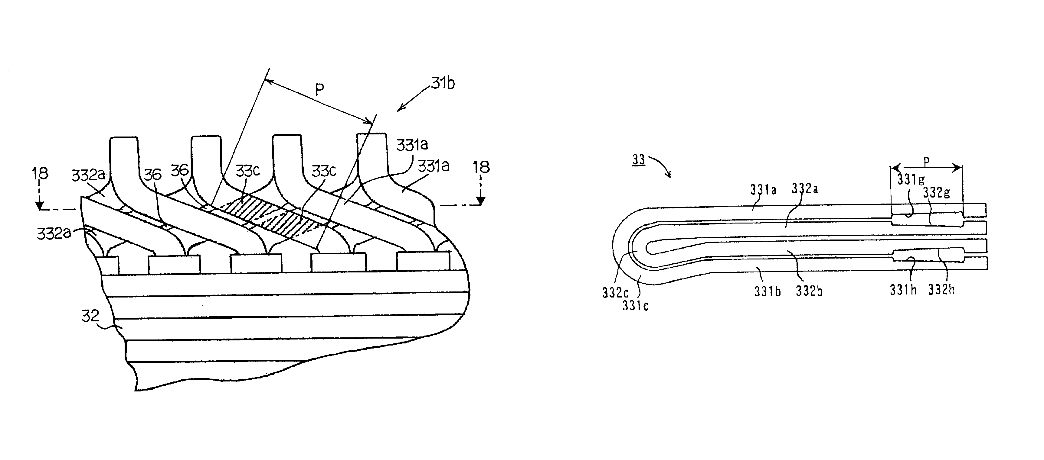
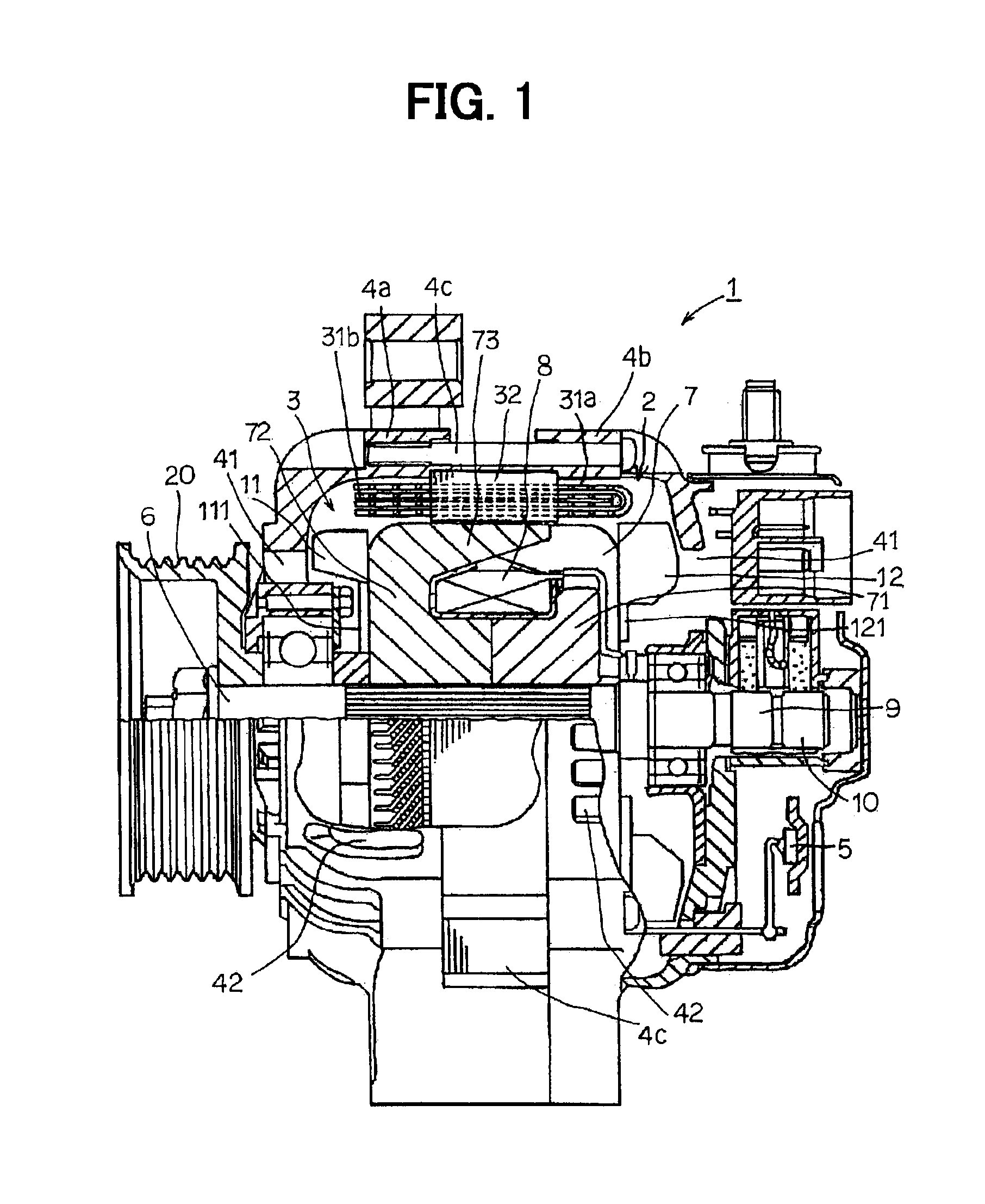
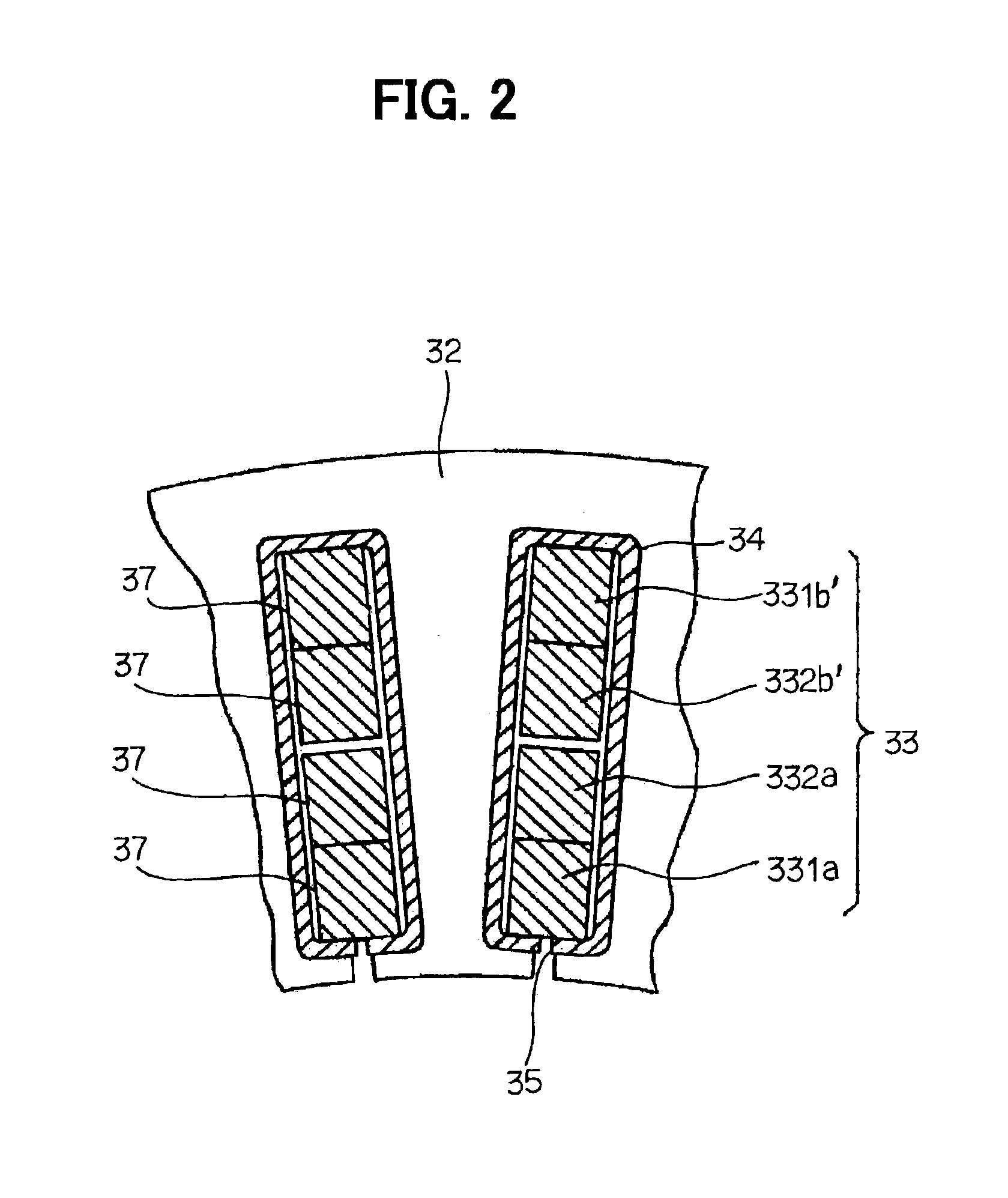
[0075]FIGS. 1 through 7 illustrate a first embodiment of the present invention, FIG. 1 is a cross-sectional view of major parts of a vehicular AC generator and FIGS. 2 through 7 are explanatory diagrams of the stator in this embodiment.

[0076]Vehicular AC generator 1 includes a stator 2 that functions as an armature, a rotor 3 as a field coil, a front housing 4a and a rear housing 4b supporting the rotor 3 and fixing the stator 2 from both sides with fastening bolts 4c, and rectifiers 5 for converting AC power into DC power. The rotor 3 rotates integrally with a shaft 6 and includes Lundell-type pole cores 7, field coils 8, slip rings 9 and 10, and an air blowing system including a diagonal current fan 11 and a centrifugal fan 12. The shaft 6 is joined to a pulley 20 and is rotated by an engine (not shown) mounted on the vehicle.

[0077]A typical Lundell-type pole core 7 has a pair of pole cores. The Lundell-type pole core 7 includes a boss 71 assembled to the shaft 6...

second embodiment

(Second Embodiment)

[0113]In a second embodiment of the present invention, even when the adjoining conductor segments at the coil end cross each other in a twisted state, clearances are secured in the intersecting portions of adjacent conductor segments by forming radial indentations.

[0114]The manufacturing process of the stator 2 of the second embodiment includes: a step of forming indentations in the side faces of each of the conductor segments 331 and 332 by pressing, the indentations being slanted so as to be oriented in the radial direction when the segments are twisted; a step of inserting the conductor segments 331 and 332 in the slots 35 so that they adjoin each other in the radial direction; a step of bending each of the conductor segments and radially adjacent segments (for example, 331a and 332a, and 332b′ and 331b′) in different circumferential directions at a predetermined pole pitch angle in a twisting fashion such that the indentations formed in the side faces of the a...

third embodiment

(Third Embodiment)

[0126]The distinguishing feature of the third embodiment is that protrusions are formed at the ends (including the bond areas) of the conductor segments at the coil end. The protrusions are offset toward the other conductor segments to be bonded.

[0127]FIG. 26 illustrates the large and small segments 331 and 332 in the third embodiment. The large and small segments 331 and 332 are respectively formed with protrusions 331k, 331l, 332k, and 3321 on the faces of the straight portions 331a, 331b, 332a, and 332b which face each other when the turn portions 331c and 332c are aligned in multiple layers. FIG. 27 is an enlarged view near the end of the large segment 331 formed with the protrusion 331l. The end of the large segment 331 is protruded, by pressing or the like, toward the side of the other conductor segment, to the bond area of which the bond area 331j of the large segment 331 will be bonded. The offset amount hl of the protrusion 331l toward that direction on th...


PUM

PropertyMeasurementUnit
bond areaaaaaaaaaaa
areaaaaaaaaaaa
radial widthaaaaaaaaaa

Abstract

To secure insulation between electrical conductors at a coil end, a first electrical conductor at one coil end is arranged so as to intersect a radially adjacent second electrical conductor at one point or more. The electrical conductor is formed with radial indentations in side faces that are opposite side faces in opposing electrical conductors at any of the intersecting portions, the indentations having depths that increase toward the near end of the electrical conductors. Sufficient clearances are thereby secured between electrical conductors in their intersecting portions near their ends where the insulating films are susceptible to damage because of welding heat. Electrical insulation is thus ensured, and the cooling efficiency at the coil end is improved.

Description

CROSS REFERENCE TO RELATED APPLICATIONS[0001]This application is based upon, claims the benefit of priority of, and incorporates by reference the contents of prior Japanese Patent Application No. 2002-9861 filed Jan. 18, 2002.BACKGROUND OF THE INVENTION[0002]1. Field of the Invention[0003]The present invention relates to a vehicular rotary electric machine, such as an AC generator for example, that is mountable on cars and trucks.[0004]2. Description of Related Art[0005]Generally, many cars are being designed with slanting hoods to minimize aerodynamic drag. Additionally, cars are also being designed with smaller engine compartments in order to provide greater interior space. As a result, there is increasingly less space available for mounting AC generators within the vehicle engine compartments. Meanwhile, increasingly lower engine revolutions (rpm) achieve increasingly better fuel economy, but reducing engine rpm also reduces the rpm of the vehicular AC generator. On the other han...

Claims


Application Information

Patent Timeline
Patent Type & Authority Patents(United States)
IPC IPC(8): H02K3/12H02K15/00H02K3/04H02K3/24H02K3/34H02K15/02H02K15/04H02K15/085H02K17/00
CPCH02K3/12H02K15/0056H02K15/0081Y10T29/49012Y10T29/49009Y10T29/53143Y10T29/49011
Inventor ICHIKAWA, MASAOKITAKADO, YASUNORIMURAHASHI, MOTOHIROFUKUDA, KAZUHIKOKATO, MITSURU
Owner DENSO CORP
Why Eureka
Try Eureka