All-analog calibration of sting-DAC linearity: application to high voltage processes

a linearity and analog calibration technology, applied in the field of digital-to-analog converters, can solve the problems of eliminating the need for costly thin film resistor trimming, and achieve the effects of reducing costs, reducing the amount of digital logic circuitry, and efficient use of semiconductor die area

Active Publication Date: 2005-05-24
TEXAS INSTR INC
View PDF8 Cites 62 Cited by
  • Summary
  • Abstract
  • Description
  • Claims
  • Application Information

AI Technical Summary

Benefits of technology

[0011]In accordance with the present invention, a system and method of calibrating a digital-to-analog converter (DAC) such as a resistor string DAC is provided that reduces costs by making more efficient use of semiconductor die area. Benefits of the presently disclosed DAC calibration technique are achieved by employing multiple calibration DACs, which are configured to minimize the amount of digital logic circuitry needed to generate a piecewise linear (PWL) approximation of the integral non-linearity error of a main DAC to be calibrated.
[0014]By employing multiple calibration DACs to minimize the amount of digital logic circuitry needed to generate a piecewise linear approximation of the integral non-linearity error of a main DAC to be calibrated, a DAC calibration circuit can be obtained that makes more efficient use of semiconductor die area and therefore reduces costs. The presently disclosed DAC calibration technique also obviates the need for costly thin film resistor trimming.

Problems solved by technology

The presently disclosed DAC calibration technique also obviates the need for costly thin film resistor trimming.

Method used


Image

  • All-analog calibration of sting-DAC linearity: application to high voltage processes
  • All-analog calibration of sting-DAC linearity: application to high voltage processes
  • All-analog calibration of sting-DAC linearity: application to high voltage processes

Examples


Embodiment Construction

[0021]U.S. Provisional Patent Application No. 60 / 484,693 filed Jul. 3, 2003 entitled CALIBRATION OF DAC LINEARITY USING PWL APPROXIMATION is incorporated herein by reference.

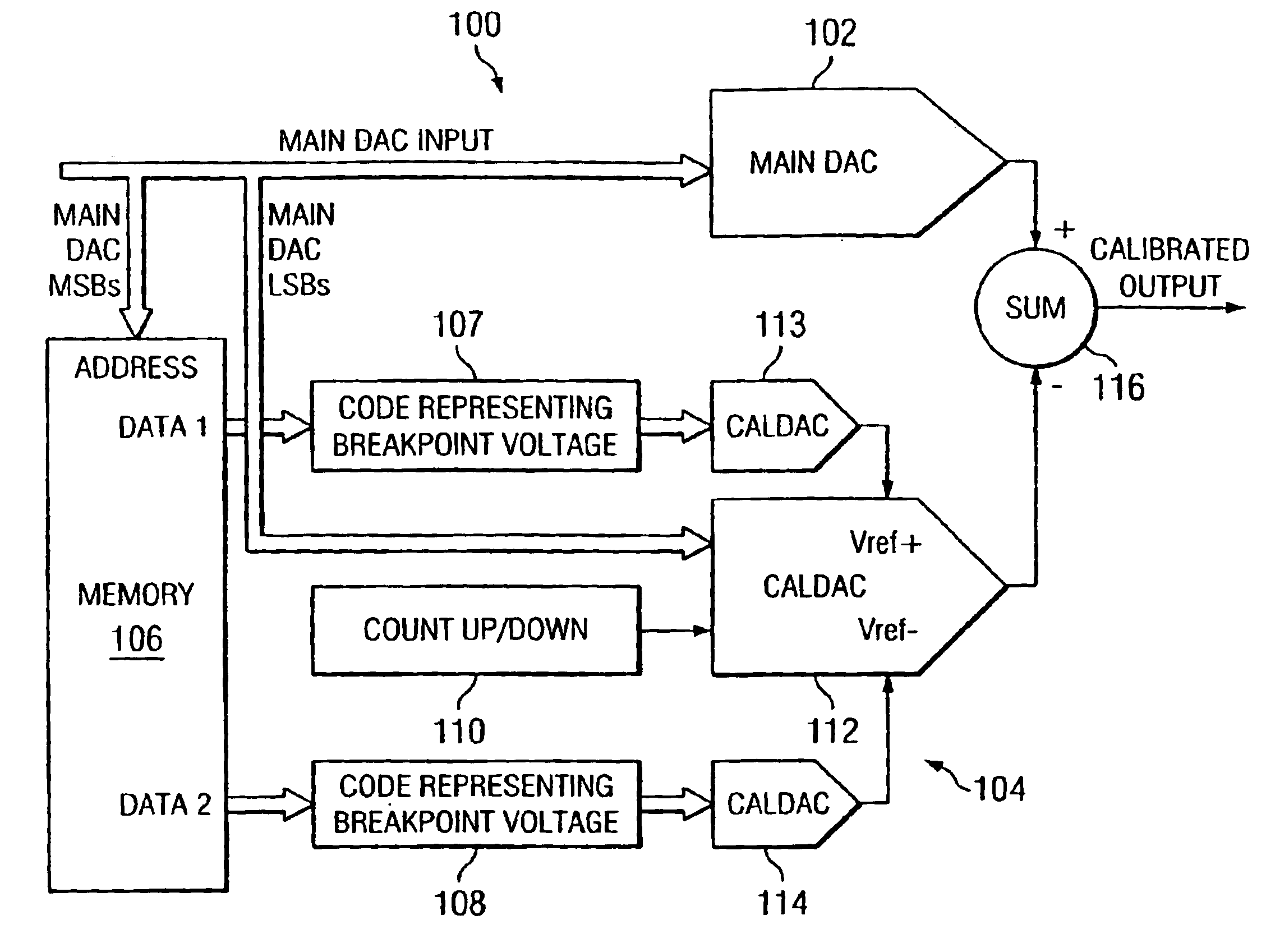
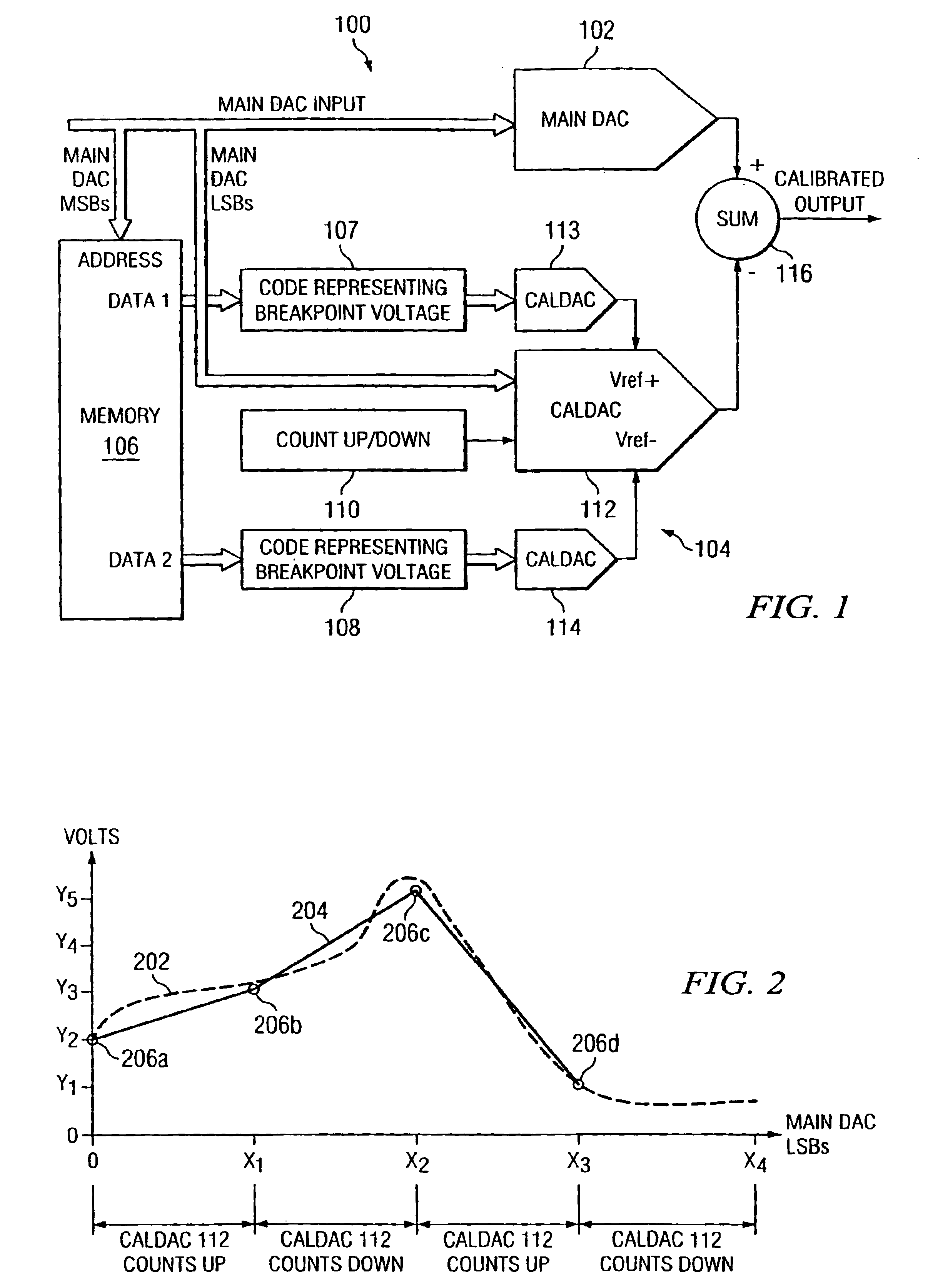
[0022]A system and method of calibrating a digital-to-analog converter (DAC) is disclosed that makes more efficient use of semiconductor die area, thereby reducing costs. The presently disclosed DAC calibration technique employs multiple calibration DACs, which are configured to minimize the amount of digital logic circuitry needed to generate a piecewise linear (PWL) approximation of the integral non-linearity error of the DAC to be calibrated.

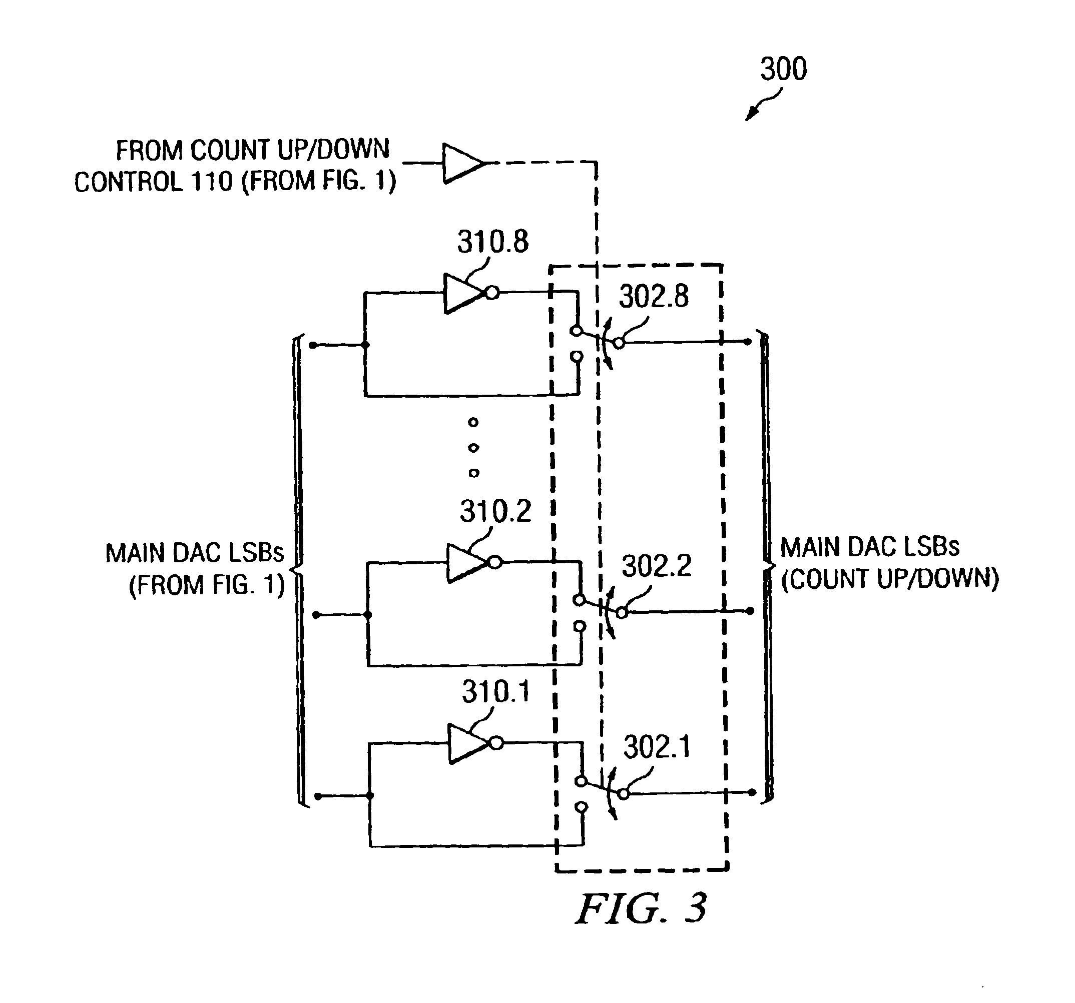
[0023]FIG. 1 depicts an illustrative embodiment of a digital-to-analog converter 100, in accordance with the present invention. In the illustrated embodiment, the DAC 100 comprises a main DAC 102 to be calibrated, and a DAC calibration circuit 104, which includes a memory 106, a pair of DAC registers 107-108, a count up / down DAC control circuit 110, a plurality of calibra...


PUM


Abstract

A system and method of calibrating a digital-to-analog converter (DAC) such as a resistor string DAC that reduces costs by making more efficient use of semiconductor die area. A digital-to-analog converter includes a main DAC to be calibrated, a memory, a plurality of calibration DACs, and an analog summing circuit. The main DAC receives digital input code values, and converts the respective input code values into an analog signal. A first calibration DAC receives a predetermined number of lower order bits of the respective input code values, and interpolates between a positive reference voltage and a negative reference voltage to generate linear waveforms for the PWL approximation. A second calibration DAC generates the positive reference voltage, and a third calibration DAC generates the negative reference voltage. The memory stores a plurality of PWL breakpoint code values representing respective integral non-linearity error values of the main DAC, and applies consecutive PWL breakpoint code values to the second and third calibration DACs, respectively, to generate the positive and negative reference voltages for the first calibration DAC.

Description

CROSS REFERENCE TO RELATED APPLICATIONS[0001]This application claims priority of U.S. Provisional Patent Application No. 60 / 484,693 filed Jul. 3, 2003 entitled CALIBRATION OF DAC LINEARITY USING PWL APPROXIMATION.STATEMENT REGARDING FEDERALLY SPONSORED RESEARCH OR DEVELOPMENT[0002]N / ABACKGROUND OF THE INVENTION[0003]The present application relates generally to digital-to-analog converters, and more specifically to an improved piece-wise linear calibration technique for resistor string digital-to-analog converters.[0004]Digital-to-analog converters (DACs) are known that employ resistor strings to convert digital input code values into analog signals. In a typical mode of operation, a conventional resistor string DAC receives digital input code values at an input of the DAC, and employs a resistor string to convert the respective digital input code values into an analog signal at an output of the DAC. Each digital input code value represents a quantized value, which is converted into ...

Claims


Application Information

Patent Timeline
Patent Type & Authority Patents(United States)
IPC IPC(8): H03M1/06H03M1/10H03M1/66
CPCH03M1/1038H03M1/66
Inventor KUYEL, TURKERYILMAZ, ABDULLAH
Owner TEXAS INSTR INC
Why Eureka
Try Eureka