Method and device for controlling voltage provided to a suspended particle device

a technology of suspended particle and voltage control device, which is applied in the direction of instruments, optics, conversion without intermediate conversion to dc, etc., can solve the problems of reducing the efficiency of the voltage control devi

Inactive Publication Date: 2005-05-24
RES FRONTIERS
View PDF12 Cites 29 Cited by
  • Summary
  • Abstract
  • Description
  • Claims
  • Application Information

AI Technical Summary

Benefits of technology

[0051]The controlling step may include linearizing the relationship between the adjustment made via the voltage level information and the selected voltage level provided to the SPD termi

Problems solved by technology

Transformers, however, tend to be rather expensive and also reduce efficiency of the voltage controlling device due to coil losses and core losses inherent in the transformer.
One problem encountered in traditional voltage controlling devices is that potentiometers provide a continuous range of voltage values between a minimum value and a maximum value such that a slight adjustment to the potentiometer results in a slight change in voltage applied to the SPD load and a corresponding slight increase in the clarity of the SPD load.
Since potentiometers are resistive circuit elements, power losses in potentiometers tend to be rather high.
In addition, the fine control provided by the potentiometer is unnecessary in an SPD application.
The human eye is not able to detect slight variations in clarity of the SPD load, thus the continuous range of voltages provided by the potentiometer which provide for minute increases in clarity of the SPD load are unnecessary.
Thus, traditional voltage controlling devices are rather inefficient and provide little observable benefit in controlling clarity of the SPD load.
While SPD loads commonly use relatively small currents, even these small currents

Method used


Image

  • Method and device for controlling voltage provided to a suspended particle device
  • Method and device for controlling voltage provided to a suspended particle device
  • Method and device for controlling voltage provided to a suspended particle device

Examples


Embodiment Construction

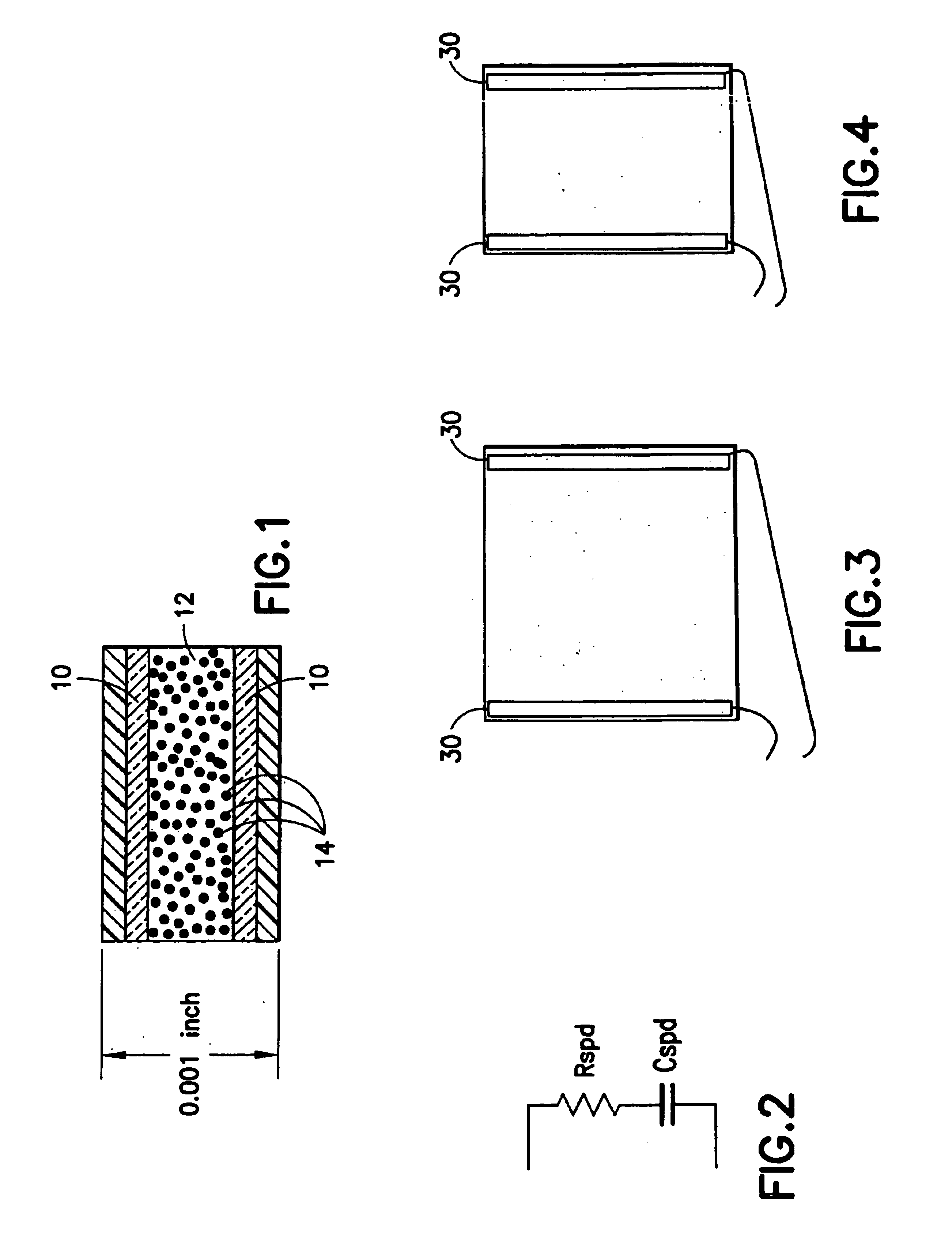
[0092]FIG. 1 illustrates an example of a typical SPD film. The two conducting layers 10 act like the two plates of a parallel-plate capacitor and the emulsion 12 acts like its dielectric. The small dots 14 represent cells (droplets) enclosing anisometrically shaped particles such as rod-shaped particles that change their orientation in the presence of an electric field. The capacitance of SPD film is given by Equation 1: Cspd=ɛ⁢AdEquation⁢ ⁢1

Where ∈ is the permittivity of the emulsion 12, A is the area of one conducting layer 10 and d is the distance between the two conducting layers 10.

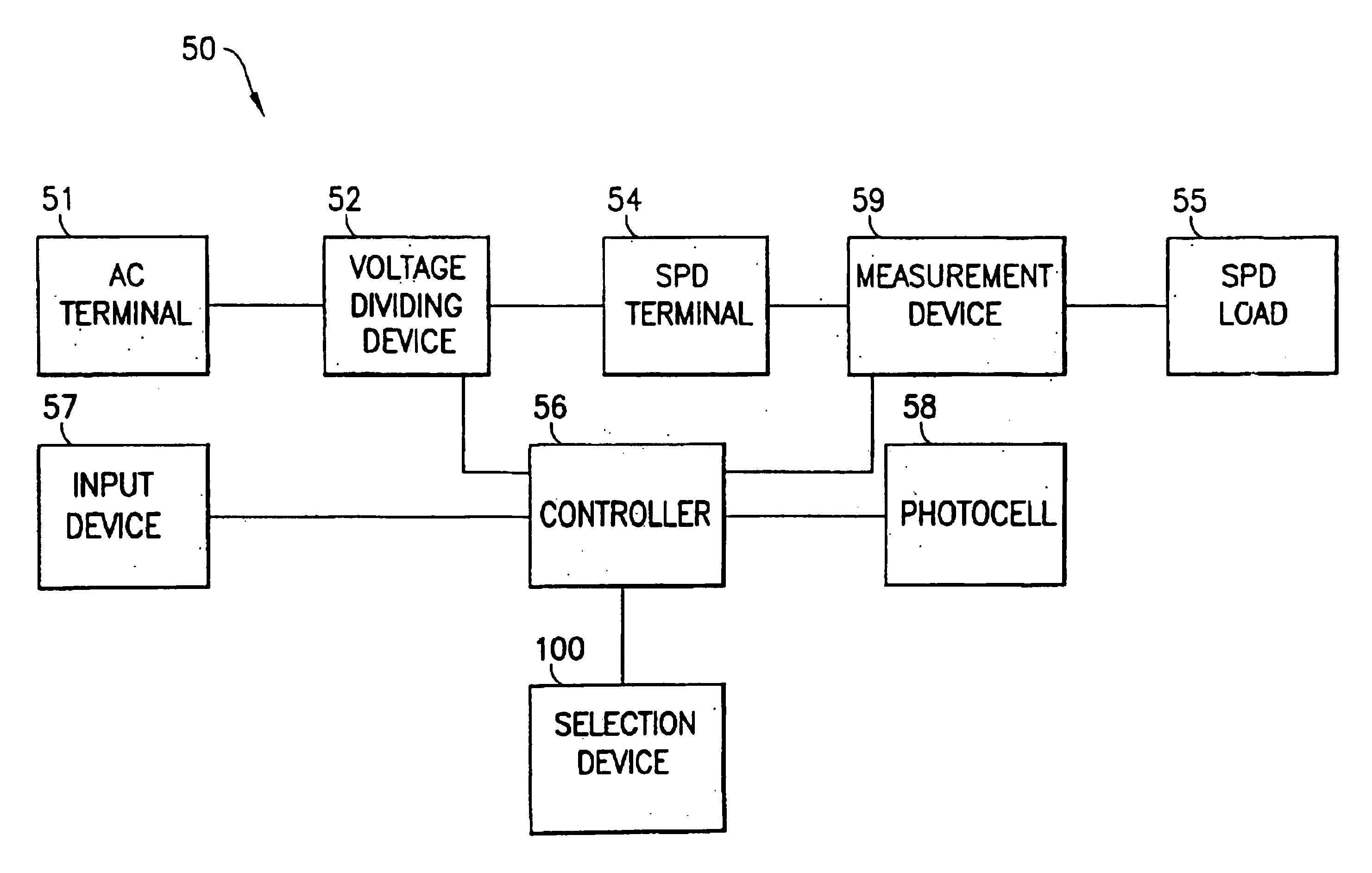
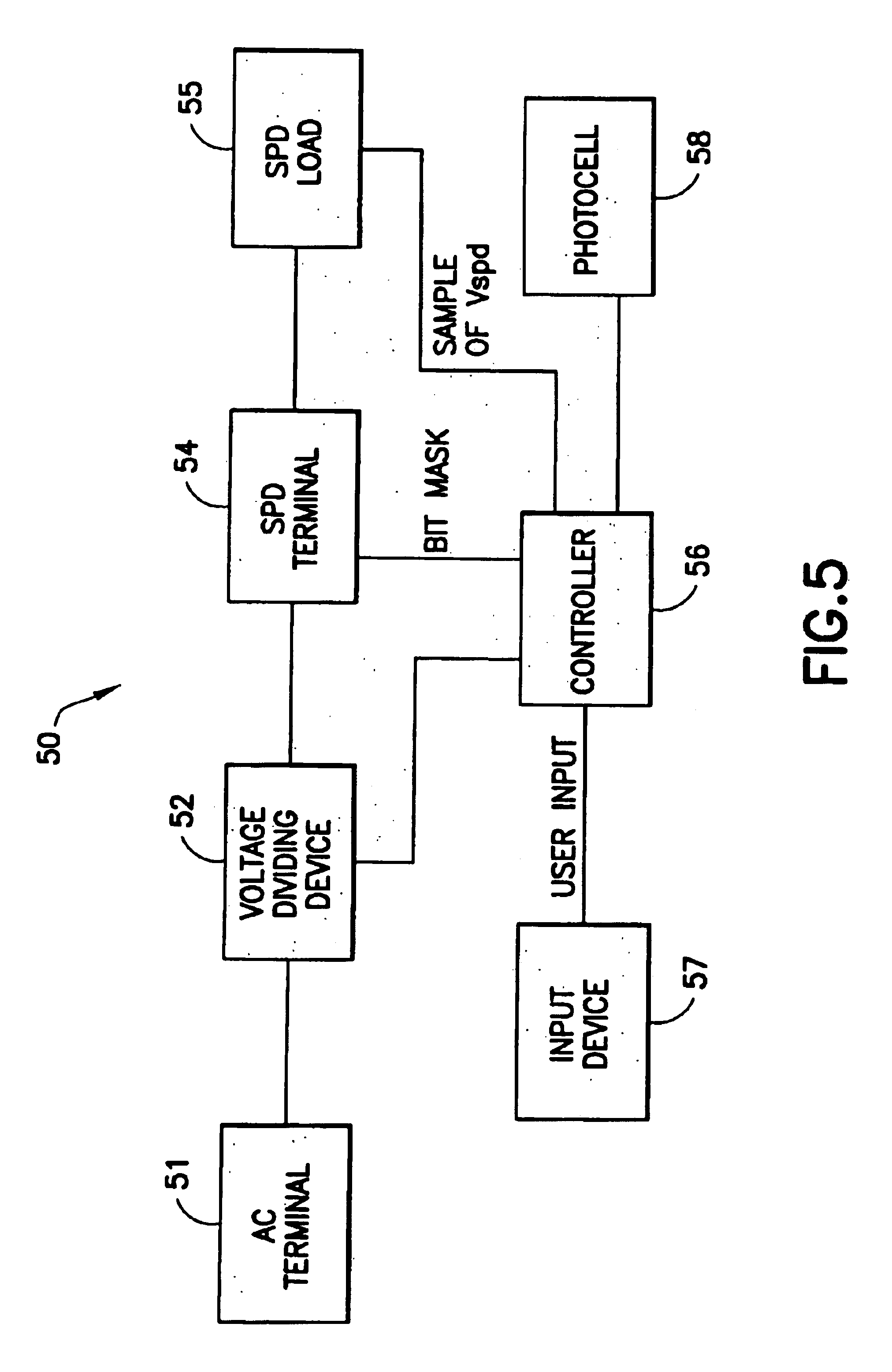
[0093]A voltage controlling device in accordance with the present invention enables one to control AC voltage applied to SPD loads in a novel, cost-effective, and safe manner. As used herein the term “SPD load” includes SPD films, SPD light valves, and all other SPD products that rely on the application of an electric field to control the orientation of suspended particles. When the electric field is...


PUM


Abstract

A voltage controlling device includes an AC terminal receiving an AC voltage signal, a voltage dividing device adapted to divide the AC voltage signal into a plurality of distinct voltage signals within a predetermined range, a controller adapted to control the voltage dividing device to provide a selected voltage level based on voltage level information and an SPD terminal for providing the selected voltage level to a suspended particle device. Voltage level information may be provided via an input device and/or from a photocell that monitors a light level at the suspended particle device. A separate AC power supply may also be provided. The controller may also monitor an SPD load voltage to control the voltage level provided to the SPD terminal in order to prevent shocking of a user.

Description

[0001]This application is a continuation-in-part of and claims the benefit of U.S. application Ser. No. 10 / 366,276 filed Feb. 13, 2003 now U.S. Pat. No. 6,804,040, the contents of which are hereby incorporated by reference.FIELD OF THE INVENTION[0002]The invention relates to a power-efficient and low-cost method and device for controlling an AC voltage applied to a suspended particle device (SPD). The invention also relates to methods and devices for shock prevention, detecting forced entry, and reducing the manufacturing costs of SPD film. The invention further relates to methods and devices for optimizing control of an AC voltage applied to a suspended particle device.BACKGROUND OF THE INVENTION[0003]Light valves have been in use for more than sixty years for the modulation of light. As used herein, a light valve is defined as a cell formed of two walls that are spaced apart by a small distance, at least one wall being transparent, the walls having electrodes thereon, usually in t...

Claims


Application Information

Patent Timeline
IPC IPC(8): G02B26/02G02F1/01G02F1/17
CPCG02F1/172G02B26/004G02B26/00H02M5/12H02M5/27
Inventor MALVINO, ALBERT P.
Owner RES FRONTIERS
Why Eureka
Try Eureka