
Radiator structure for a computer device

a computer device and radiator technology, applied in the direction of electrical apparatus casings/cabinets/drawers, power cables, semiconductor/solid-state device details, etc., can solve the problems of heat needs to be radiated, computer devices to shut down, and up too much space, so as to reduce the size of the radiator structure, increase space usability, and reduce the effect of siz

Inactive Publication Date: 2005-05-24
TATUNG COMPANY
View PDF3 Cites 6 Cited by
  • Summary
  • Abstract
  • Description
  • Claims
  • Application Information

AI Technical Summary

Benefits of technology

[0007]A main objective of the present invention is to provide a radiator structure, which can reduce the size of the radiator structure to permit micro miniaturization designs and increase space usability.
[0008]Another objective of the present invention is to provide a radiator structure, which absorbs contact pressure by way of resilience of a radiator board to decrease the number of parts and manufacturing costs.
[0012]In the present invention, the radiator board replaces the prior art cooling fin, and requires less space without reducing cooling efficiency. Micro miniaturization designs can thus be achieved, and the space efficiency is increased. Moreover, the deforming section of the radiator board provides an resilient force to absorb a contact pressure generated between the radiator board, the conductive plate and the exothermal unit, so that the present invention does not need springs, which reduces both the total number of parts and the manufacturing costs of the entire radiator structure.

Problems solved by technology

This generated heat needs to be radiated, as it will otherwise cause the computer device to shut down.
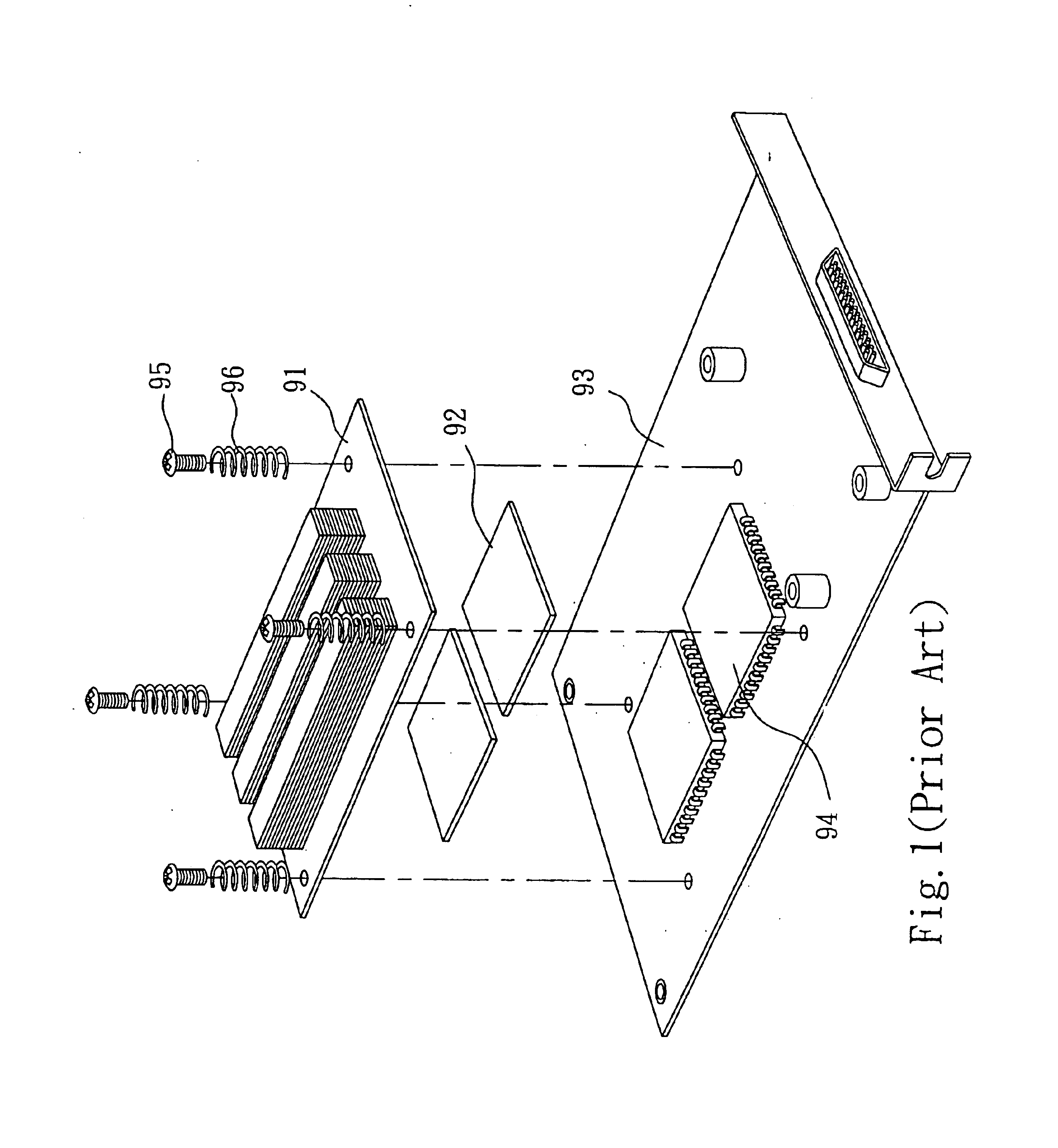
However, the prior art cooling fin 91 takes up too much space, and thus does not permit micro miniaturization designs.
Consequently, different exothermal chips 94 require different springs 96 with different design characteristics, which increases the total number of fixing parts for the cooling fin 91, and also increases the manufacturing costs.

Method used


Image

  • Radiator structure for a computer device
  • Radiator structure for a computer device
  • Radiator structure for a computer device

Examples


Embodiment Construction

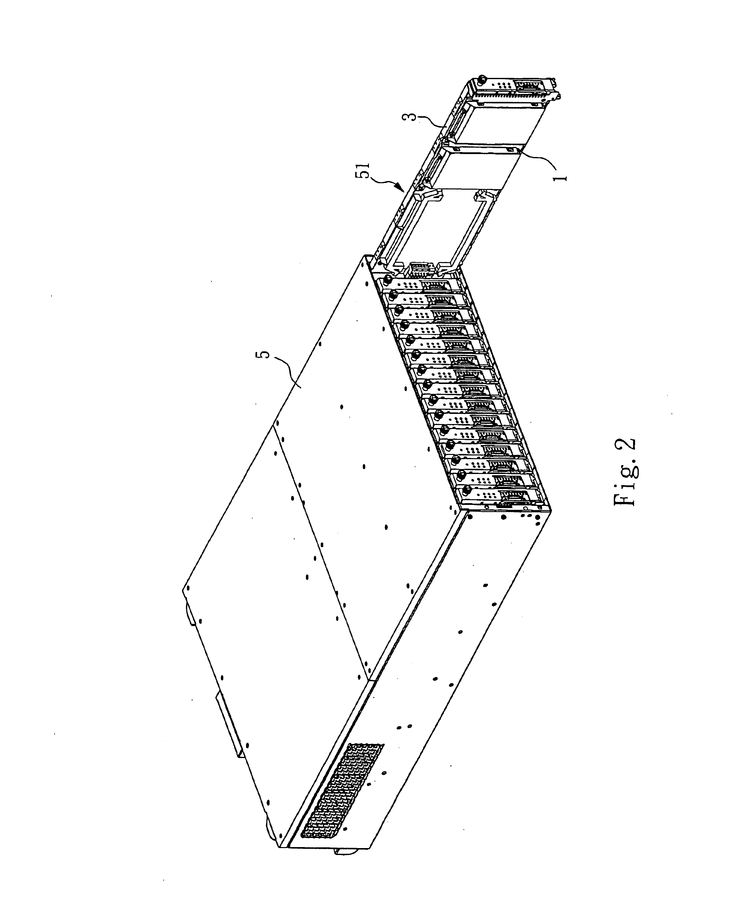
[0020]Please refer to FIG. 2. FIG. 2 is a schematic drawing of the present invention used in a blade server. A blade server 5 (a computer device) has a plurality of server blades 51. A radiator structure of the present invention is placed on each server blades 51.

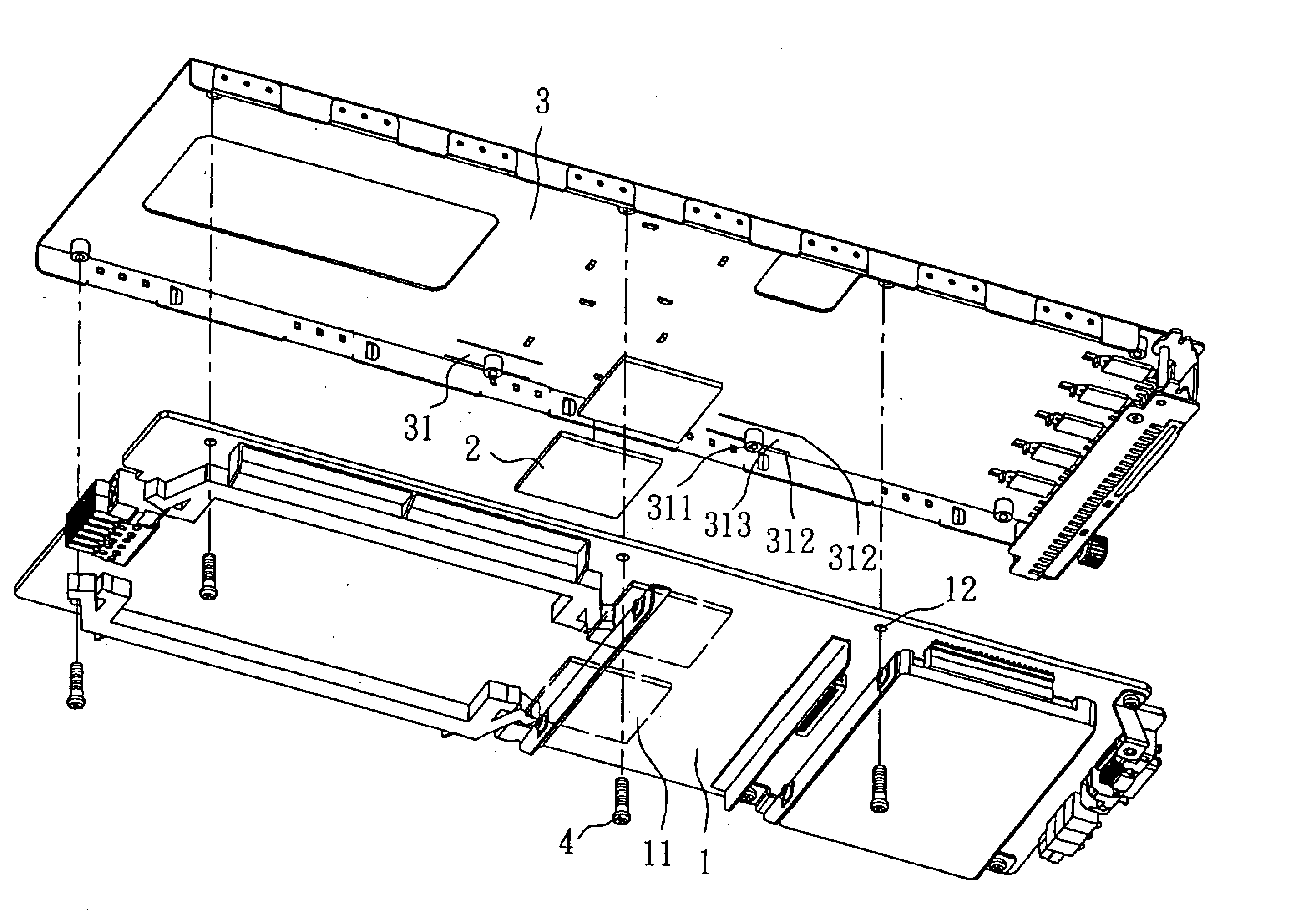
[0021]Please FIG. 3, FIG. 4 and FIG. 5. FIG. 3 is an exploded view of the present invention. FIG. 4 is another exploded view of the present invention. FIG. 5 is a sectional drawing of the present invention when locked. In the drawings, one of the server blade 51 is taken out and decomposed. The radiator structure comprises a circuit board 1, two conductive plates 2, a radiator board 3 and four screws 4 (lock attachments). The circuit board 1 further comprises two microprocessor chips 11 (exothermal units) installed thereon and four apertures 12. Each microprocessor chip 11 generates differing amounts of heat. Each aperture 12 is spaced at a predetermined distance from the two microprocessor chips 11, and two conductive plat...


PUM


Abstract

A radiator structure has a circuit board, at least one conductive plate, a radiator board and at least two lock attachments, and reduces the entire radiator structure size to permit micro miniaturization designs and increase the space efficiency without affecting cooling efficiency. The radiator board has a deforming section, which undergoes resilience deformation facing the circuit board to absorb a contact pressure generated between the radiator board, the conductive plate and the microprocessor chip. Use of a spring to absorb the contact pressure is thus not required, which decreases the number of parts and manufacturing costs.

Description

BACKGROUND OF THE INVENTION[0001]1. Field of the Invention[0002]The present invention relates to a radiator structure and, more particularly, to a radiator structure that is suitable for a desktop computer, a notebook computer, a plate computer, and similar computer devices, and which is especially suited for a blade server.[0003]2. Description of Related Art[0004]In a computer device, such as a desktop computer, a notebook computer, a plate computer or a blade server, cooling is always a significant concern for research and design engineers, as the most recent microprocessor chips used in these computer devices have higher and higher clock speeds, which lead to the generation of more and more heat. This generated heat needs to be radiated, as it will otherwise cause the computer device to shut down.[0005]The prior art cooling method utilizes a cooling fin. Please refer to FIG. 1. FIG. 1 is an exploded view of a prior art cooling structure. A cooling fin 91 is adhered to an exotherm...

Claims


Application Information

Patent Timeline
Patent Type & Authority Patents(United States)
IPC IPC(8): G06F1/20H01L23/40H01L23/34
CPCG06F1/20H01L23/4006H01L2023/405H01L2023/4062H01L2924/0002H01L2023/4081H01L2924/00
Inventor LIU, WEN-CHINCHOU, YI-LUNG
Owner TATUNG COMPANY
Learn More