Semiconductor integrated circuit with voltage generation circuit, liquid crystal display controller and mobile electric equipment

Inactive Publication Date: 2005-05-24
SYNAPTICS JAPAN GK
View PDF9 Cites 47 Cited by
  • Summary
  • Abstract
  • Description
  • Claims
  • Application Information

AI Technical Summary

Benefits of technology

[0013]To add, where the aforementioned positive voltage system (FIG. 14A) is used, the semiconductor substrate can be biased with a ground potential instead of a negative voltage. This would result in application of a stable ground potential to the substrate potential supply region 114b shown in FIG. 15 from immediately after the beginning of power supply application, with no fear of the parasitic transistor Qs2 being turned on, so that the prevention of latch-up phenomena due to the parasitic thyristors accompanying the CMOS circuitry need not be so strict as in a negative voltage system. Other possible latch-up prevention measures include, in addition to circuits according to the present invention, a double well structure (PWELL is set to the negative voltage VCOML and the P-type the substrate 100, to the ground potential GND), deepened well regions or some contrivance the device structure in the configuration of FIG. 15, and they can prevent latch-up to some extent, but they would involve a more complex process or require a sophisticated process technique for accurately controlling the well depth, inviting an increased cost of the semiconductor chip.
[0032]According to a third aspect of the invention under the present application, there is provided mobile electric equipment provided with the liquid crystal display control unit having the above-described configuration, a liquid crystal panel to perform displaying in a dot matrix system in accordance with a signal generated by the segment drive circuit and a signal generated by the common electrode drive circuit; and a battery for providing the source voltage of the liquid crystal display control unit. This makes it possible to realize mobile electric equipment with high display picture quality, consuming less power and capable of operating on a battery for many hours.

Problems solved by technology

However, a system illustrated in FIG. 14C was found to involve the problem that, where a CMOS circuit is used, it would be susceptible to a latch-up phenomenon.

Method used


Image

  • Semiconductor integrated circuit with voltage generation circuit, liquid crystal display controller and mobile electric equipment
  • Semiconductor integrated circuit with voltage generation circuit, liquid crystal display controller and mobile electric equipment
  • Semiconductor integrated circuit with voltage generation circuit, liquid crystal display controller and mobile electric equipment

Examples


Embodiment Construction

[0048]Preferred embodiments of the present invention will be described below with reference to accompanying drawings.

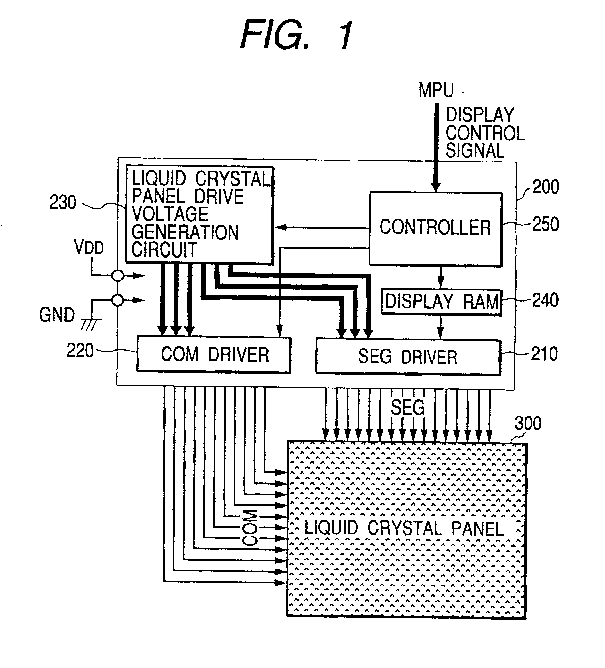
[0049]First, as an example of a semiconductor integrated circuit having a built-in power supply circuit of booster type to which the invention can be effectively applied, a semiconductor integrated circuit 200 for liquid crystal display control will be described with reference to FIG. 1. FIG. 1 is a block diagram illustrating the configuration of a liquid crystal display unit consisting of the liquid crystal panel controller driver 200 with the built-in power supply circuit of booster type to which the invention can be effectively applied and a liquid crystal panel 300 driven by this driver.

[0050]In FIG. 1, reference numeral 200 denotes the liquid crystal panel controller driver LSI, and 300, the liquid crystal panel driven by this liquid crystal panel controller driver LSI 200. The liquid crystal panel controller driver LSI 200 is provided with, among other elements,...


PUM


Abstract

There is to be provided a liquid crystal drive controller with a built-in power supply circuit wherein latch-up is made difficult to arise even if one amplitude level of the segment line drive voltage is set to the ground potential and the levels of other liquid crystal drive voltages are determined accordingly. A semiconductor integrated circuit with a built-in power supply circuit, wherein a negative voltage generated in a power supply circuit is applied to a substrate or a well region as a bias voltage, is provided with a switch for temporarily applying the ground potential to the substrate or well region to be biased with the negative voltage at the time of starting up the power supply circuit.

Description

BACKGROUND OF THE INVENTION[0001]The present invention relates to a latch-up preventive technique for use in a semiconductor integrated circuit with a built-in booster type power supply circuit for generating a voltage resulting from boosting of the source voltage, such as an LSI (large scale semiconductor integrated circuit) for liquid crystal display control with a built-in power supply circuit for liquid crystal display driver, and a technique that can be effectively applied to mobile electric equipment mounted with such an LSI.[0002]Nowadays, as a displaying unit for mobile electric equipment including mobile telephones and pagers, a dot matrix type liquid crystal panel in which a plurality of display pixels are two-dimensionally arrayed in a matrix form for instance is usually employed, and the equipment is mounted with a display control unit, integrated into a semiconductor circuit, for controlling the displaying on this liquid crystal panel of a driver circuit for driving the...

Claims


Application Information

Patent Timeline
IPC IPC(8): G09G3/36G02F1/133G09G3/20H01L21/822H01L27/04
CPCG09G3/3611G09G3/3622G09G3/3696H02M3/07G09G2310/0245G09G2310/0278H02M2003/071G09G2330/02G09G2330/021G09G2330/026G09G2310/08H02M3/071G09G3/36H02M1/00G09G2300/0408
Inventor ENDO, KAZUYAMIYAMOTO, NAOKIMIZUNO, TOSHIONAKAJI, TAKAYUKIUCHIDA, TAKATOSHIOOKADO, KAZUOYOKOTA, YOSHIKAZU
Owner SYNAPTICS JAPAN GK
Why Eureka
Try Eureka