Induction furnace for high temperature operation

a high-temperature operation, furnace technology, applied in the direction of furnaces, lighting and heating apparatus, electric/magnetic/electromagnetic heating, etc., can solve the problems of pyrometer failure, furnaces operating at temperatures over 3000° c., prone to failure, need recalibration, etc., to reduce cool down time, easy to remove from the furnace, and increase the effect of furnace li

Inactive Publication Date: 2005-05-24
GRAFTECH INT HLDG INC
View PDF14 Cites 8 Cited by
  • Summary
  • Abstract
  • Description
  • Claims
  • Application Information

AI Technical Summary

Benefits of technology

[0012]In accordance with yet another aspect of the present invention, an induction furnace is provided. The furnace includes a susceptor which defines an interior chamber for receiving items to be treated, the susceptor being formed from graphite. An induction coil induces a current in the susceptor to heat the susceptor. A layer of flexible graphite, exterior to the susceptor, inhibits escape of carbon vapor which has sublimed from the susceptor.
[0014]An advantage of at least one embodiment of the present invention is that significant increases in furnace life are obtained.
[0015]Another advantage of at least one embodiment of the present invention is that cool down times are reduced.
[0016]Another advantage of at least one embodiment of the present invention is that the cooling assembly is readily removable from the furnace, simplifying removal and replacement of the susceptor and other hot zone components.
[0017]Other advantages of at least one embodiment of the present invention derive from greater accuracy in monitoring variations in furnace temperature throughout the furnace.

Problems solved by technology

There is a tendency, however, for the graphite to sublime, turning to vapor.
Thus, furnaces which are operated at temperatures of over 3000° C. tend to suffer considerable downtime for replacement of components.
However, pyrometers are prone to failure and need recalibration over time.
However, because the furnace is generally well insulated, it often takes about a week to cool the furnace down from its operating temperature.
This system works well for furnaces' that are rarely operated above 2800° C. In furnaces that are routinely operated above 3000° C., the frequent replacement of hot zone components renders these designs expensive to operate.

Method used


Image

  • Induction furnace for high temperature operation
  • Induction furnace for high temperature operation
  • Induction furnace for high temperature operation

Examples


Embodiment Construction

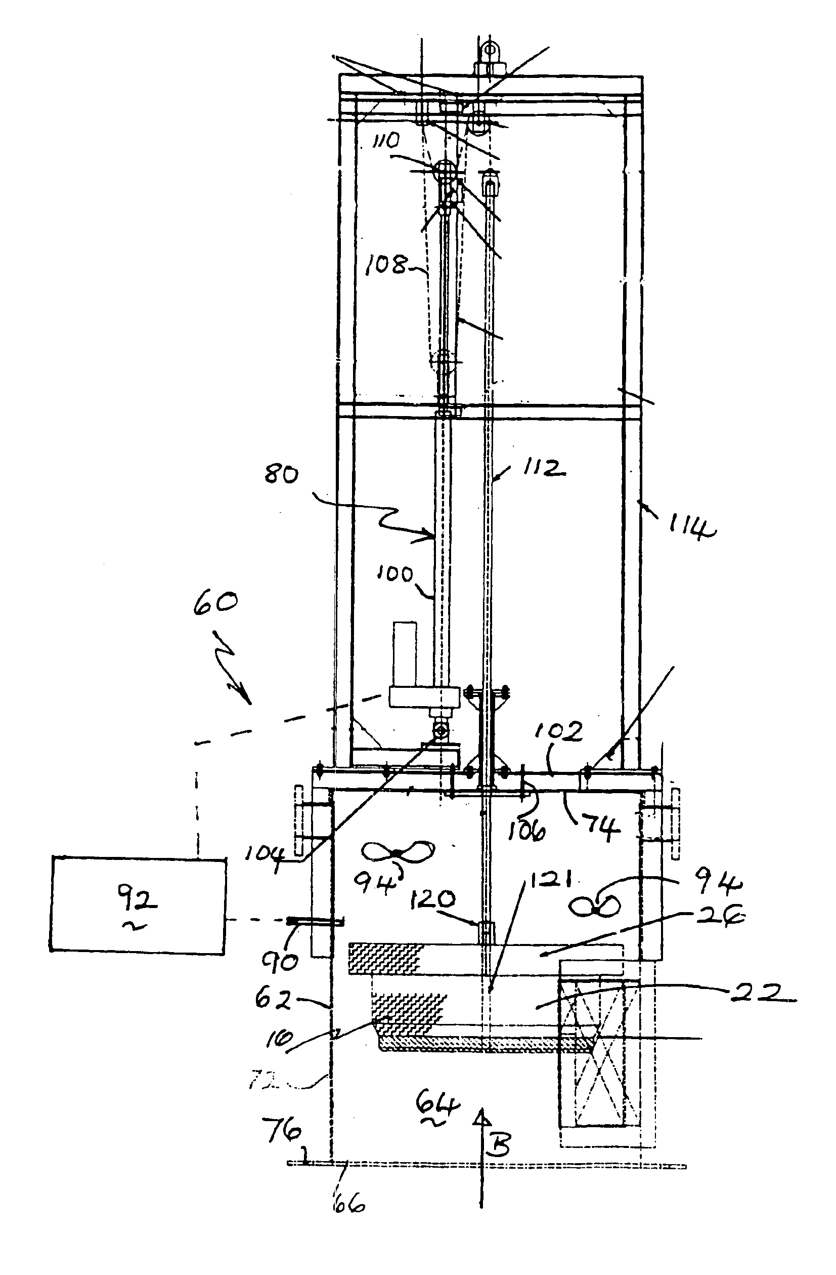
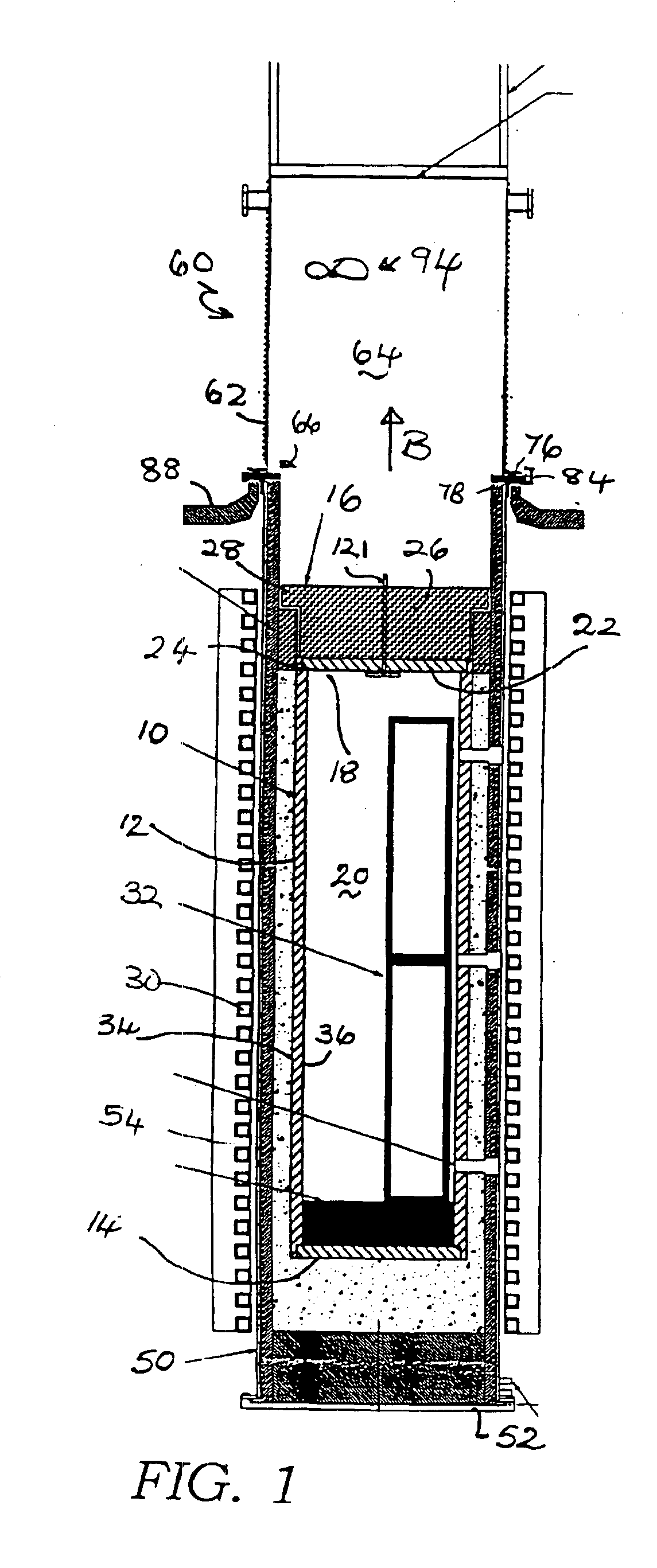
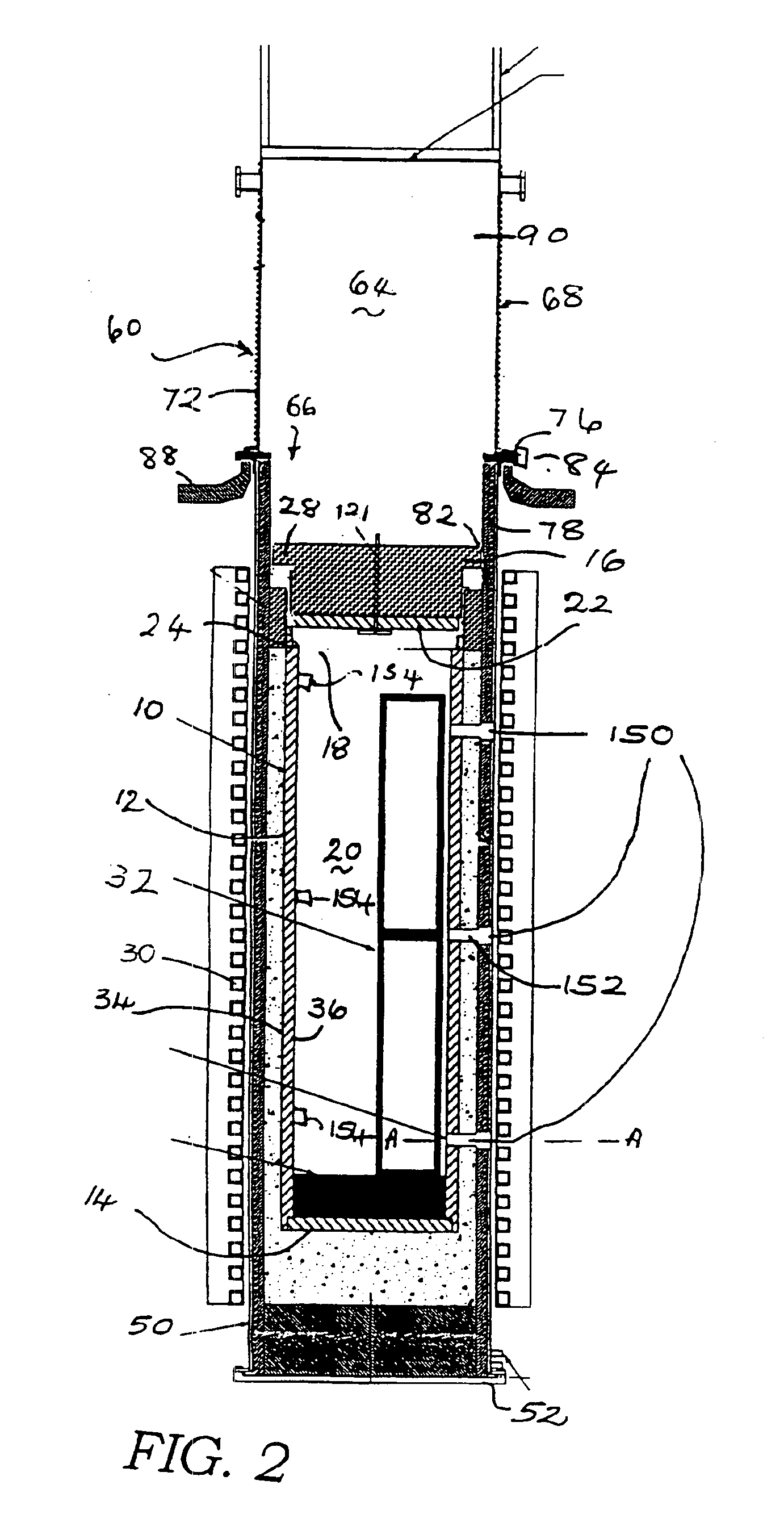
[0030]With reference to FIGS. 1 and 2, an induction furnace suited to operation at temperatures of over 3000° C. includes a susceptor 10 formed from an electrically conductive material, such as graphite. The susceptor includes a cylindrical side wall 12 closed at a lower end by a base 14. A removable insulative cap 16 closes an upper open end 18 of the susceptor to define an interior chamber 20, which provides a hot zone for receiving items to be treated. The cap 16 includes a lid portion 22, formed from graphite, which seats on a shelf 24 defined by the susceptor adjacent the upper end 18. The lid portion 22 is attached to a lower surface of an enlarged insulative plug 26, preferably formed from a rigid insulation material, such as graphite rigid insulation. The plug 26 has an outwardly extending peripheral flange at its upper end. The cap 16 closes the interior chamber 20 during a heating phase of an induction furnace operating cycle, allowing the furnace to operate under a slight...


PUM

PropertyMeasurementUnit
temperatureaaaaaaaaaa

Abstract

An induction furnace capable of operation at temperatures of over 3100° C. has a cooling assembly (60), which is selectively mounted to an upper end of the furnace wall (76). The cooling assembly includes a dome (62), which is actively cooled by cooling water coils (68). During the cool-down portion of a furnace run, cooling initially proceeds naturally, by conduction of heat away from the hot zone through a furnace insulation layer (58). Once the temperature within the furnace hot zone (20) reaches about 1500° C., a lifting mechanism (80), mounted to the dome, raises a cap (16) of the furnace slightly, allowing hot gases from the hot zone to mix with cooler gas in the dome. This speeds up cooling of the hot zone, reducing cool-down times significantly, without the need for encumbering the furnace itself with valves or other complex cooling mechanisms which have to be replaced periodically. The life of a graphite furnace susceptor (10) at the high operating temperature is increased by surrounding the susceptor with a barrier layer (40) of flexible graphite, which inhibits evaporation of the graphite. Additionally, witness disks (154), placed within the susceptor, provide an accurate temperature profile of the hot zone.

Description

[0001]This is a divisional of application Ser. No. 10 / 115,694 entitled “Induction Furnace For High Temperature Operation,” filed Apr. 4, 2002 now U.S. Pat. No. 6,724,803.BACKGROUND OF THE INVENTION[0002]1. Field of the Invention[0003]The invention relates to an induction furnace suited to operation at temperatures of around 3000° C. and above. It finds particular application in conjunction with the graphitization of pitch fibers and other carbon-containing fibers and will be described with particular reference thereto. It should be appreciated, however, that the furnace is also suited to other high temperature processes, such as halogen purification of graphitic materials to remove metal impurities.[0004]2. Discussion of the Art[0005]Batch induction furnaces have been used for many years for fiber graphitization and other high temperature operations. A typical induction furnace includes an electrically conductive vessel, known as a susceptor. A time-varying electromagnetic field is ...

Claims


Application Information

Patent Timeline
Patent Type & Authority Patents(United States)
IPC IPC(8): D01F9/32D01F9/14F27B14/00F27B14/06F27D23/00F27D9/00C01B31/04H05B6/10F27B17/00F27D1/12F27D7/06F27D11/06F27D21/00F27D99/00
CPCD01F9/322F27B14/061F27D2099/002F27D2009/0018
Inventor MILLER, DOUGLAS J.RUOFF, WERNER H.INTERMILL, ALLAN WEBSTERSTRONG, STEPHEN L.THOMAN, THOMAS R.SHAO, RICHARD L.
Owner GRAFTECH INT HLDG INC
Why Eureka
Try Eureka