Computational and
hardware complexity and cost have limited the provision of adjustability and / or
adaptive behavior of known
flicker filter arrangements and thus do not eliminate
flicker under all conditions or accommodate different display standards.
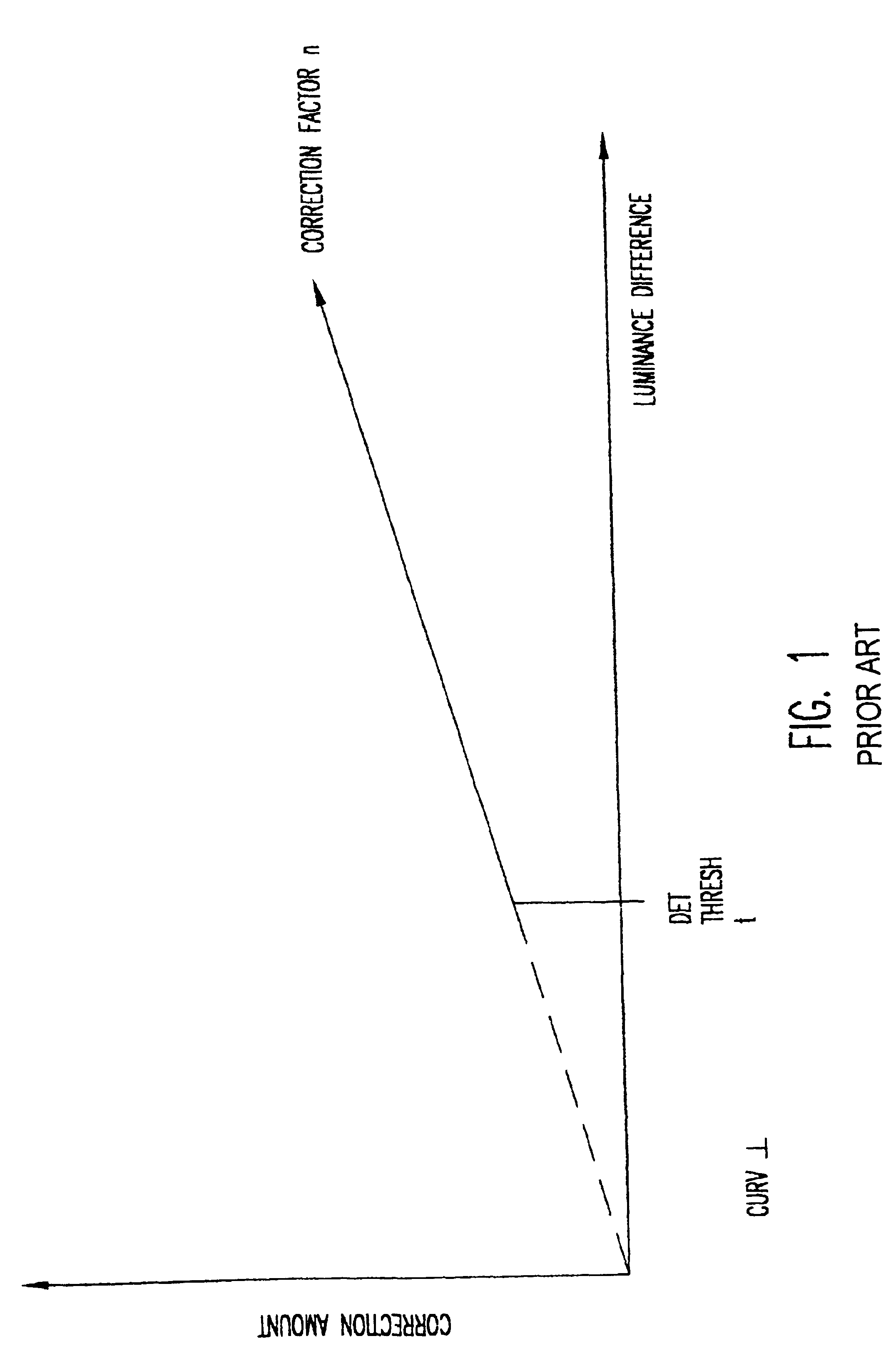
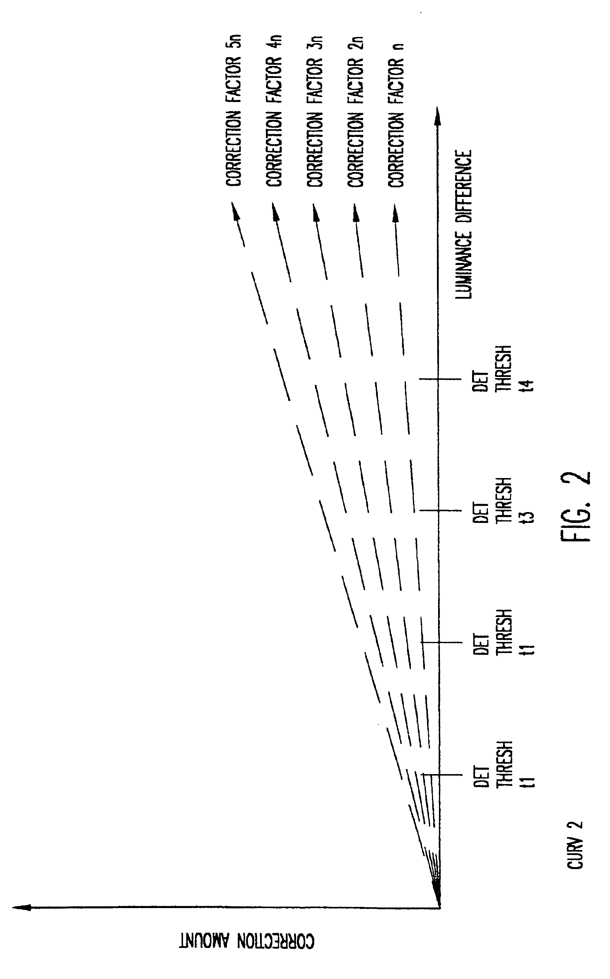
Conversely, filter transfer functions of flicker filters of acceptable simplicity and economy generally exhibit discontinuities such as the step discontinuities of FIGS. 1-3 which engender other objectionable artifacts and / or compromise image fidelity while providing differing degrees of flicker reduction.
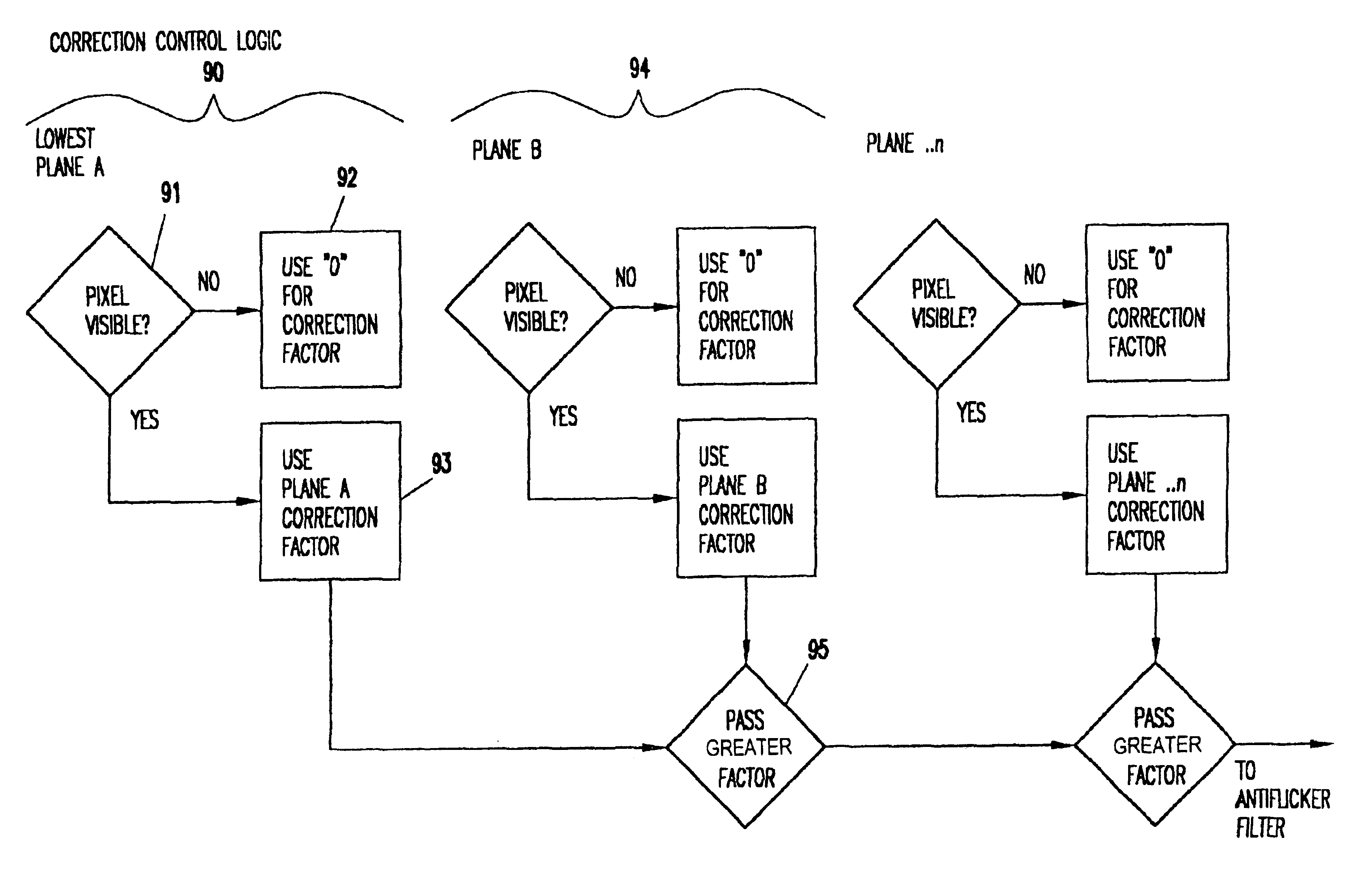
It should be recognized that the comparison of two vertically adjacent pixel luminance values requires storage of luminance values (either original or corrected) corresponding to an entire interlaced field (one-half of all pixels displayed) as well as a substantial computational burden which must be performed in substantially real time.
Such storage capacity can only be achieved with substantial hardware cost even though special purpose chips for such purposes are commercially available.
Further problems are associated with multiple images.
However, such an approach would require storage of a full interleaved field of each image and substantial computational overhead which would not contribute to the final displayed image (e.g. the portion of the large image occluded by smaller images).
However, while possibly reducing computational burden and allowing application of different correction factors, this approach blurs the interlaced fields.
Therefore, the image would be of very
poor quality if used on computer generated
graphics images and only marginally acceptable with video images; requiring different treatment by a
programmer or user.
The flicker filter selection problem is at its worst when the set-top box is being used for
Internet access by presenting multiple planes of web-based images and text while simultaneously viewing a downscaled MPEG video
stream or still image while a background plane may be showing a video
stream or still image that has not been downscaled.
However, such an approach would require double sampling, as alluded to above, for each
image plane and storage hardware would become prohibitive to do so for far fewer than the number of planes (e.g. five or more) it is much preferred to provide.
Additionally, as alluded to above, while a processor of substantial power is necessary in a set-top box for decompression and error
recovery or concealment in substantially real time, the
processing demands of such a function are very substantial and may vary quickly when
digital image transmissions are made over a lossy medium such as
the Internet.
Therefore, it can be seen that the amount of
image processing hardware required to provide features demanded by the market is very extensive and of very substantial cost even when special purpose chips are manufactured in production quantities.
Present hardware presents substantial difficulties in implementing flicker filters which may also require extensive hardware for only marginally satisfactory performance.
The on-
chip microprocessor cannot realistically be used to implement flicker filters and no filtering arrangement is known that can be implemented at an economically viable cost which does not cause a trade-off between the severity of different types of artifacts or which is reasonably effective on all ranges of contrast differences in all types of images and, in particular, images which can be manipulated at the will of the user in a manner which will generally alter the likelihood of production of objectionable flicker effects and the severity thereof.

