Image binarization apparatus, image binarization method, image pickup apparatus, image pickup method, and a computer product

a binarization apparatus and binarization method technology, applied in the field of image binarization apparatus image binarization method, etc., can solve the problems of inability to apply uniform correction, easy shadow and brightness unevenness in the photographed image, and inconvenient use, etc., to achieve high-quality binarization of multi-valued images and low power consumption

Inactive Publication Date: 2005-05-24
RICOH KK
View PDF9 Cites 54 Cited by
  • Summary
  • Abstract
  • Description
  • Claims
  • Application Information

AI Technical Summary

Benefits of technology

[0012]It is an another object of the present invention to perform high quality binarization of a multi-valued image rapidly and at a low rate of power consumption.

Problems solved by technology

However, the problems described below exist in the conventional technology.
Namely, the number, position, and strength of the light sources are different, and therefore shadows and brightness unevenness easily occur in the photographed image.
Moreover, because the shadows and brightness unevenness are inconstant, it is not possible to apply uniform correction as with the scanner section of a photocopier machine or the like.
Accordingly, images photographed using a digital camera have the problem that high quality binarization is not possible.
Moreover, even if images have been photographed using a homogeneous light source, peripheral light reduction is caused by the properties of the optical system resulting in the problem arising that uniform correction and high quality binarization are not achievable.
Accordingly, there is the problem that the processing load has substantial increased and the processing speed has consequently decreased.
Accordingly, there is the problems that considerable processing resources are required and the rate of power consumption is also high.

Method used


Image

  • Image binarization apparatus, image binarization method, image pickup apparatus, image pickup method, and a computer product
  • Image binarization apparatus, image binarization method, image pickup apparatus, image pickup method, and a computer product
  • Image binarization apparatus, image binarization method, image pickup apparatus, image pickup method, and a computer product

Examples


first embodiment

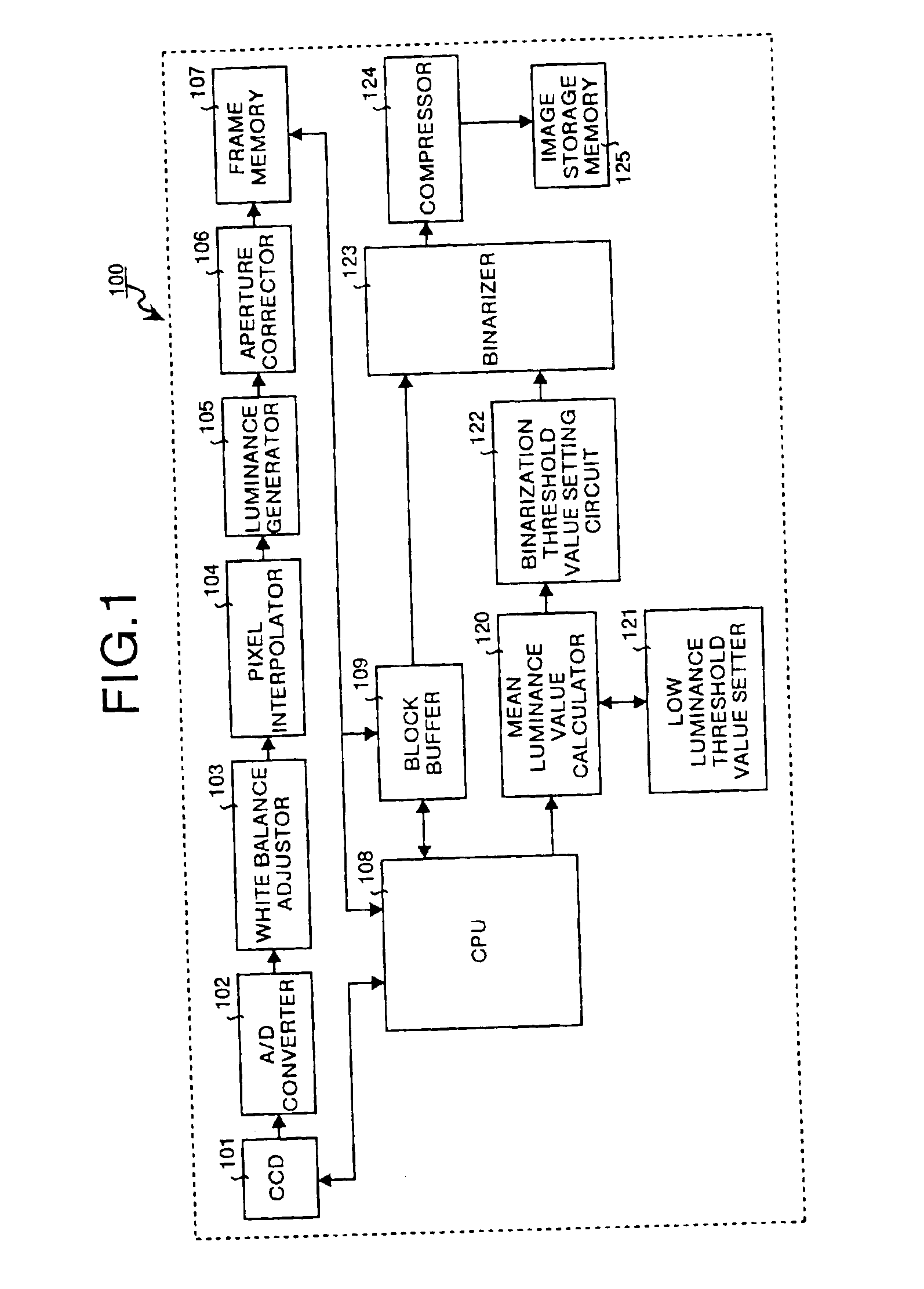
[0060]The first embodiment explained below relates to an image binarization apparatus of the present invention which is used in a digital camera. FIG. 1 is a block diagram showing an example of the apparatus structure from the input of image data until a binarized image (binarized data) is recorded when an image binarization apparatus of the present invention is used in a digital camera.

[0061]A digital camera 100 comprises a CCD 101, an A / D converter 102, a white balance adjustor 103, a pixel interpolator 104, a luminance generator 105, an aperture corrector 106, frame memory 107, a CPU 108, a block buffer 109, a mean luminance value calculator 120, a low luminance threshold value setter 121, a binarization threshold value setting circuit 122, a binarizer 123, a compressor 124, and an image storage memory 125.

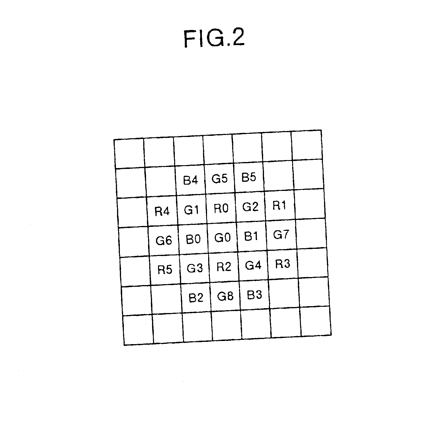
[0062]The CCD 101 converts light converged by a not shown optical system of the digital camera 100 into electric signals and outputs R, G, B analog signals for each pixel formi...

second embodiment

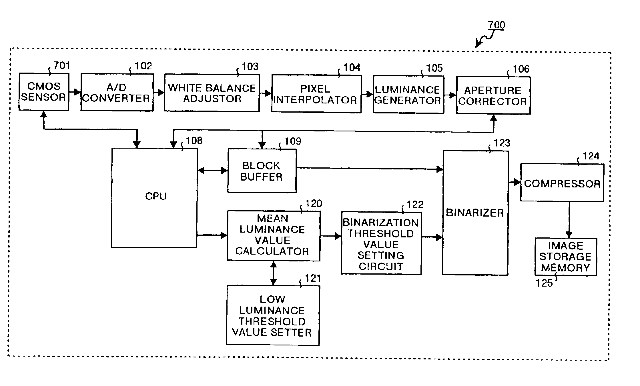
[0118]Note that, in the present embodiment, a CCD 101 is used, however, depending on the mode of use, it is also possible to use a CMOS sensor 701 (see FIG. 7) as in the

[0119]In this sixth embodiment, the description given is of when a digital camera uses an image binarization apparatus in which binarization threshold values applied to each pixel in a predetermined block are calculated and binarization of the image data performed for each pixel, with the spread of the mean luminance values limited so as to be within a predetermined range. FIG. 13 is a block diagram showing an example of the structure of a digital camera according to the present embodiment. Note that portions of the structure of the present embodiment which are identical to those of the fifth embodiment are given the same symbols and a description thereof is omitted.

[0120]The digital camera 1300 is provided with a limiter 1301 which limits the mean luminance values output from the mean luminance value calculator 120 ...

fourth embodiment

[0122]Note that, in the present embodiment, a CCD 101 is used, however, depending on the mode of use, it is also possible to use a CMOS sensor 1101 (see FIG. 11) as in the

[0123]The seventh embodiment explained below relates to an image binarization apparatus having a photometry unit. FIG. 14 is a block diagram showing an example of the apparatus structure from an image input until a recording of a binarized image when an image pickup apparatus provided with a photometer is used in a digital camera. Note that, in the present embodiment, because the structural elements are similar to those of the first embodiment, the same structural elements as those of the first embodiment are given the same symbols and a detailed description thereof is omitted. Those portions that are different to the first embodiment are mainly described.

[0124]The digital camera 1400 comprises the CCD 101, the A / D converter 102, the white balance adjustor 103, the pixel interpolator 104, the luminance generator 10...


PUM


Abstract

In a digital camera, a CPU divides a multi-valued image into blocks and selects object blocks, which are to be the object of processing. A CCD outputs luminance values of the multi-valued image. A low luminance threshold value setter sets low luminance threshold values on the basis of mean luminance values of blocks adjacent to the object block. A mean luminance value calculator calculates mean luminance values using luminance values from which luminance values that do not reach the low luminance threshold value in a block have been removed. A binarization threshold value setting circuit sets a binarization threshold value of the block based on the mean luminance values. A binarizer then binarizes the multi-valued image in the block on the basis of the binarization threshold values.

Description

FIELD OF THE INVENTION[0001]The present invention relates to an image binarization apparatus, an image pickup apparatus, an image binarization method, an image pickup method, and a computer product. More particularly, this invention relates to a technology an image is binarized after removing the shadows and unevenness in the brightness of a multi-valued image input using an image input apparatus having an inconstant light source.BACKGROUND OF THE INVENTION[0002]Conventionally, when saving a document as an electronic document generally a scanner, a camera, or the scanner section of a facsimile machine is used as an image input apparatus. In this type of scanner (scanner section), a light source is provided inside the apparatus and light emitted from the light source which is reflected from the document (original) is read by a CCD or the like. If necessary, the read image is then binarized and saved. Because the characteristics of the used light source and optical system are constant...

Claims


Application Information

Patent Timeline
Patent Type & Authority Patents(United States)
IPC IPC(8): H04N1/403G06T1/00G06V30/10G06V30/162H04N5/225
CPCH04N1/403G06K9/38G06V30/10G06V30/162
Inventor TAKAHASHI, SADAO
Owner RICOH KK
Why Eureka
Try Eureka