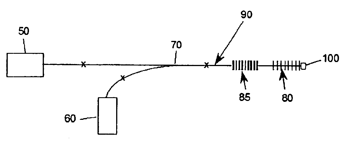
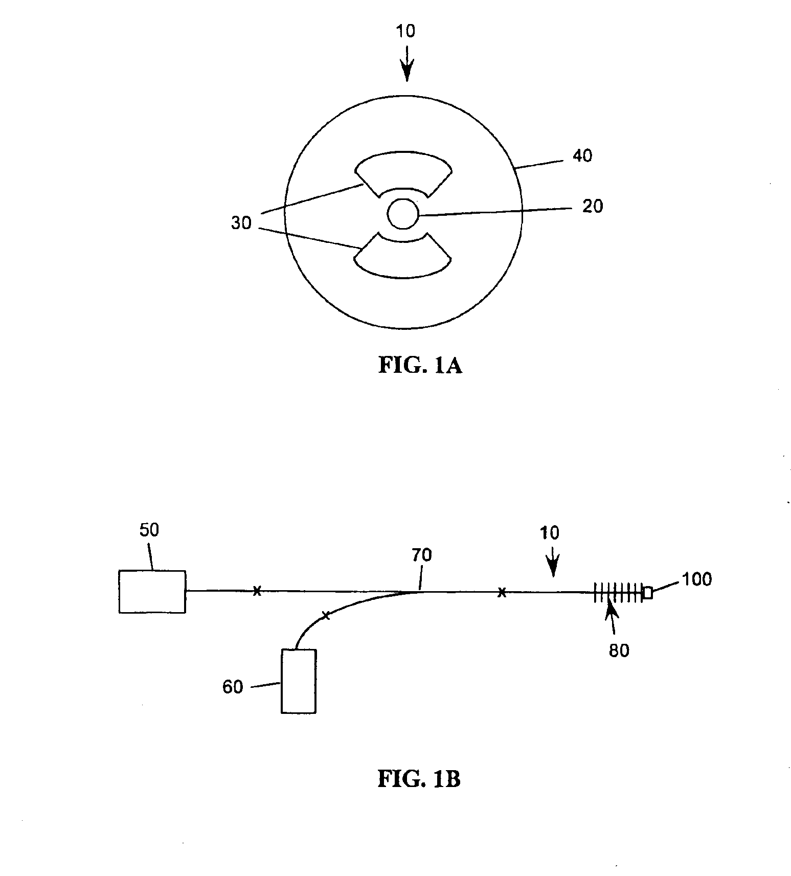
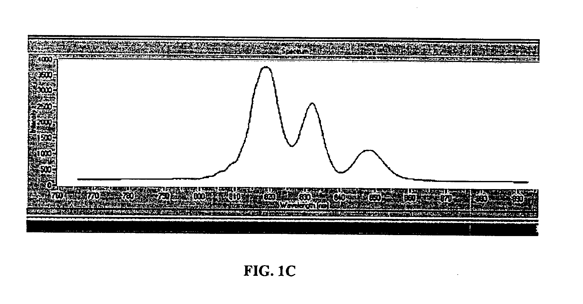
Fiber-optic apparatus and method for making simultaneous multiple parameter measurements

a fiber optic and measurement method technology, applied in the field of fiber optic methods and apparatuses for simultaneous multiple parameter measurement, can solve the problems of inability to distinguish between different parameters, limited methods, and inability to separate the effects of changes

Active Publication Date: 2005-05-24
LUNE INNOVATIONS INC +1
View PDF12 Cites 93 Cited by
  • Summary
  • Abstract
  • Description
  • Claims
  • Application Information

AI Technical Summary

Problems solved by technology

This method is limited to single sensing depths because only one polarization state can transfer energy into the metallic layer of the SPR sensor.
In the case of a LPG system, only one binding depth could be detected and there was no way to distinguish between ...

Method used


Image

  • Fiber-optic apparatus and method for making simultaneous multiple parameter measurements
  • Fiber-optic apparatus and method for making simultaneous multiple parameter measurements
  • Fiber-optic apparatus and method for making simultaneous multiple parameter measurements

Examples


example 1

[0086]To demonstrate different sensing field depths for different wavelengths, tests were performed through sandwiching of IgG antibodies. To experimentally determine sensing depts. For the various long period grating (LPG) sensors, antibody sandwich layers were applied to the LPG sensor until there was no minimal shift in wavelength (1 / e point). The LPG was constructed with a 69 micron period for the 820 nm response and a 136 micron period for the 1530 nm sensor. Fibers were prepared using a methanol wash for one hour and were then silated with aminopropylsilane. A goat-anti-rabbit antibody was covalently attached through EDAC chemistry. Alternating layers of goat-anti-rabbit and rabbit-anti-goat were then applied by exposing the fibers to samples at 100 μg / ml. FIG. 6A depicts the response decay for anti-rabbit / rabbit anti-goat antibody binding for the 820 nm system and FIG. 6B depicts the response decay for the 1530 nm system. The 820 nm systems illustrates 12 layers for antibody ...

example 2

[0087]The method of the present invention was employed to measure thickness on a cylindrical object by long period grating (LPG) changes in thin film coating systems. To measure the sensing depth of the sensor, an ionically self-assembled monolayer (ISAM) coating process consisting of alternating layers of cations and anions was employed. Poly(diallyldimethyl ammonium choloride) (PDDA) and Poly(sodium 4 styrenesulfonate) (PSS) were selected for their stability between wet and dry states. In order to verify the thickness of each bilayer, several silicon wafers were cleaned and varying ISAM layers were applied to the wafer. Measurements were made using an ellipsometer. The following procedure was used to coat 40, 70, and 90 bilyaers on three different slides. Thickness was then measured using an ellipsometer. Once measurements were taken, the same procedure was used to coat the LPG sensors to determine the evanescent sensing depths.

[0088]All wafers / sensors were initially cleaned using...


PUM


Abstract

A fiber-optic method for making simultaneous multiple parameter measurements employs an optical fiber sensor having at least one long period grating disposed therein. An excitation is created in the optical fiber sensor wherein a plurality of evanescent field sensing depths result. At least two long period grating signatures are created. When the optical fiber sensor is exposed to at least one material, changes in the material are identified by simultaneously measuring and comparing shifts in each long period grating signature; correlating the shifts to changes in the material; and solving a series of equations that compare changes in the coupling wavelength for a specific loss band. A reactive coating may be applied to the optical fiber sensor proximate to the long period grating such that changes in the reactive coating as it reacts with the material may also be monitored.

Description

CROSS-REFERENCE TO RELATED APPLICATIONS[0001]This application claims the benefit of U.S. Provisional Patent Application Ser. No. 60 / 455,470, entitled “Optical Fiber Sensor Arrangement for Multiple Parameter Measurement,” filed Mar. 19, 2003, which is hereby incorporated by reference in its entirety.FIELD OF THE INVENTION[0002]The present invention relates to a fiber-optic method and apparatus for making simultaneous multiple parameter measurements. In particular, the invention is directed towards measuring and comparing shifts in long period grating signatures as an optical fiber is exposed to a material and correlating such shifts to various changes in the material.BACKGROUND OF THE INVENTION[0003]It is often desirable to have the ability to measure changes in materials as they undergo various chemical and biological reactions in real time. Direct detection is one method employed for such measurements and is typically based on optical techniques that respond to changes in refractiv...

Claims


Application Information

Patent Timeline
IPC IPC(8): G01D5/353G01D5/26G01N33/487G01N33/543
CPCG01D5/35303G01D5/35383G01N33/54373
Inventor AVERETT, JOSHUA P.ELSTER, JENNIFER L.JONES, MARK E.PENNINGTON, CHARLES D.VAN TASSELL, ROGER L.
Owner LUNE INNOVATIONS INC
Why Eureka
Try Eureka