
Articles useful as optical waveguides and method for manufacturing same

a technology of optical waveguides and optical waveguides, which is applied in the direction of optical waveguide light guides, optical elements, instruments, etc., can solve the problem of altering the output intensity of the waveguid

Inactive Publication Date: 2005-05-24
CALIFORNIA INST OF TECH
View PDF14 Cites 0 Cited by
  • Summary
  • Abstract
  • Description
  • Claims
  • Application Information

AI Technical Summary

Benefits of technology

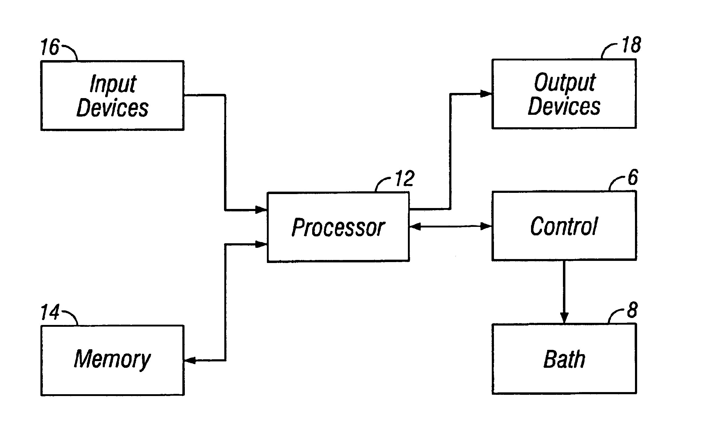
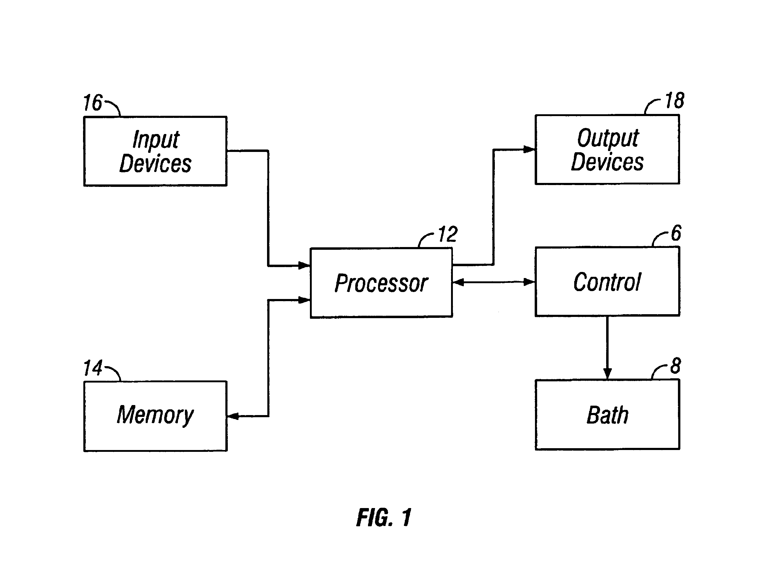
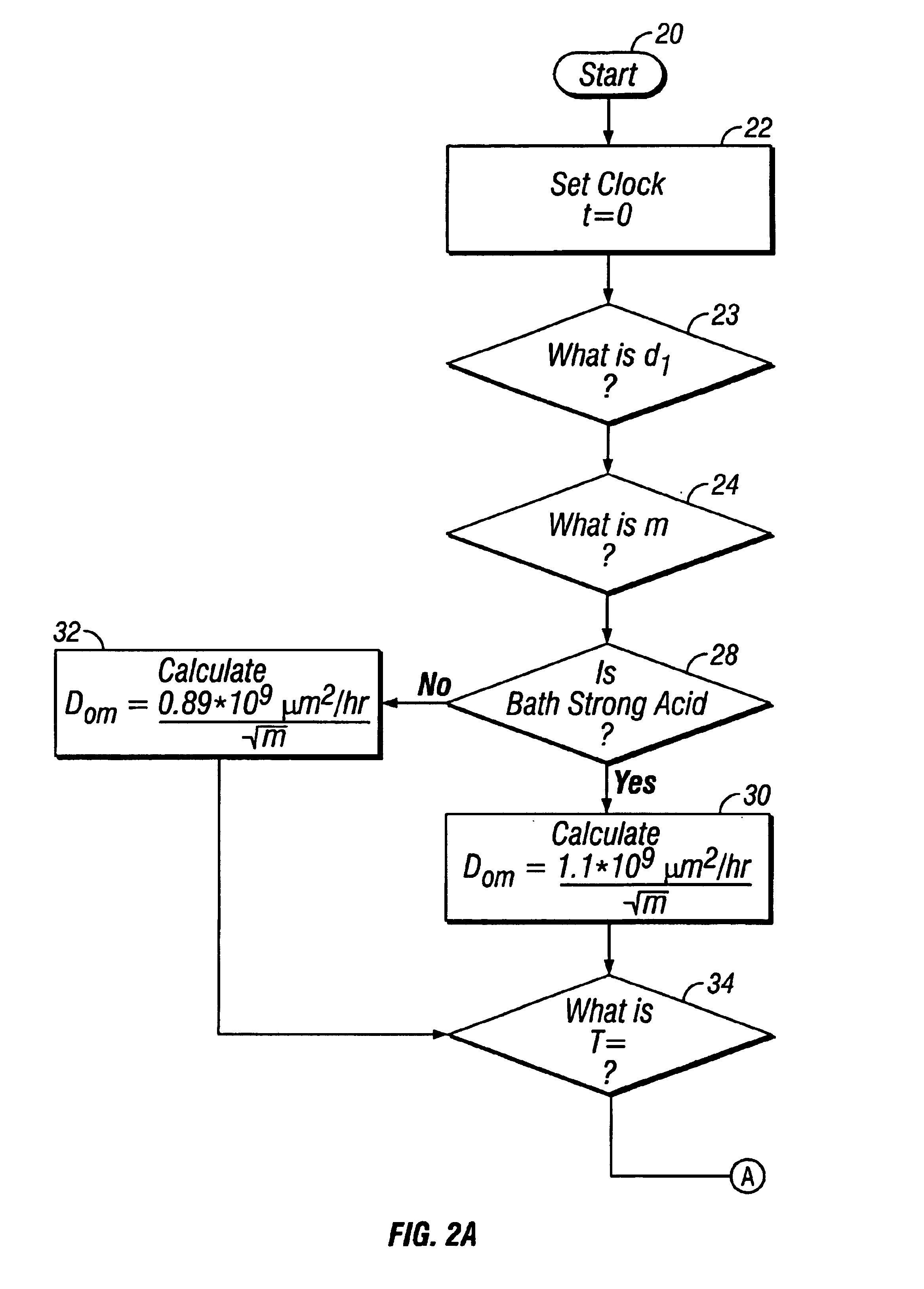
[0013]In other aspects, the present invention is directed to the calculation, storage and retrieval of data for determining the depth of diffusion of lithium displacing ions in a crystalline substrate that includes lithium ions, and for use in a method for fabricating an optical waveguide. The data and control processes of the invention can be implemented by a software application program executed in

Problems solved by technology

As a result, optical waveguides, the refractive index, and the region of guide itself tend to drift over time, which alters the output intensity of the waveguide.

Method used


Image

  • Articles useful as optical waveguides and method for manufacturing same
  • Articles useful as optical waveguides and method for manufacturing same
  • Articles useful as optical waveguides and method for manufacturing same

Examples


example 1

[0035]Optical waveguides were prepared as follows. A LiNbO3 substrate ({circumflex over (Z)}-cut) was immersed in a bath of deuterated sulfuric acid (98% purity (Aldrich)) located in an oven. The oven temperature was ramped from 23° C. at a rate of 0.5° C. / min to a temperature of 160° C., held at 160° C. for a period of about 190 minutes and cooled to a temperature of 20° C. at a rate of 1° C. / min. The etched substrate was rinsed with distilled water to remove excess acid. The deuterium ion exchange depth was calculated to be 0.19 um.

[0036]The treated substrate was then placed in an oven, and the oven temperature was ramped from 23° C. to 360° C. at a rate of 1° C. / min, held at 360° C. for a period of two hours, and cooled to 20° C. at a rate of 1° C. / min under an atmosphere of dry oxygen.

[0037]The treated substrate was then subjected to a second anneal in which the temperature of the oven was ramped from 23° C. to 360° C. at a rate of 1° C. / min, held at 360° C. for a period of four...

example 2

[0039]A 2001 Å layer of SiO2 was deposited on a 1 in.×0.3 in. LiNbO3 wafer, patterned using lithographic techniques, and etched using a reactive ion etch to expose a pattern of the LiNbO3 substrate. The etched substrate was then cleaned with acetone.

[0040]The LiNbO3 substrate was then immersed in a bath of deuterated sulfuric acid (98% purity (Aldrich)) located in an oven. The oven temperature was ramped from 23° C. to 160° C. at a rate of 0.5° C. / min, held at 160° C. for a period of 191 minutes, and cooled to a temperature of 20° C. at a rate of 1° C. / min. The etched substrate was rinsed with distilled deuterated water to remove excess acid. The deuterium ion exchange depth was calculated to be 0.19 um.

[0041]The treated substrate was then annealed by placing the substrate in an oven, and ramping the oven temperature from 23° C. to 360° C. at a rate of 1° C. / min. The oven temperature was held at 360° C. for a period of four hours and then cooled to 20° C. at a rate of 1° C. / min unde...


PUM

PropertyMeasurementUnit
Structureaaaaaaaaaa
Electric propertiesaaaaaaaaaa
Magnetismaaaaaaaaaa

Abstract

A method for manufacturing an article capable of constraining a propagating wave is disclosed. The method includes contacting a crystalline substrate with a source of deuterium ions to create a region in the crystalline substrate having a crystal structure that includes deuterium ions. The region is capable of constraining a propagating wave to the region.

Description

CROSS-REFERENCE TO RELATED APPLICATION[0001]This is a divisional application of U.S. patent application Ser. No. 09 / 157,652, entitled “Articles Useful as Optical Waveguides and Method for Manufacturing Same,” filed on Sep. 21, 1998 in the name of the same inventor and assigned to the same assignee, now issued as U.S. Pat. No. 6,518,078 B2 on Feb. 11, 2003.STATEMENT AS TO RIGHTS TO INVENTIONS[0002]The United States Government has certain rights in this invention pursuant to Grant No. F19628-95-C-0002 awarded by the United States Air Force.BACKGROUND OF THE INVENTION[0003]This invention relates to preparing crystalline substrates useful for optical waveguides.[0004]Crystalline LiNbO3 and LiTaO3 are used in optical waveguides. Integrated optic circuits based upon such optical waveguides are useful in various electrooptical devices including, e.g., fiber optic gyros (FOGs), photonic switching devices, and intensity / phase modulation systems. A variety of methods exist for fabricating LiN...

Claims


Application Information

Patent Timeline
IPC IPC(8): G02B6/13G02B6/134G02B6/12
CPCG02B6/1342G02B2006/12045G02B2006/1204
Inventor BURROWS, LEE J.
Owner CALIFORNIA INST OF TECH
Learn More