Magnetic alloy material and method of making the magnetic alloy material

a magnetic alloy and alloy material technology, applied in the field of magnetic alloy materials, can solve the problems of long sintering time, low productivity, and low productivity, and achieve the effects of rapid solidification, easy pulverization, and short tim

Inactive Publication Date: 2006-10-19
HITACHI METALS LTD
View PDF4 Cites 130 Cited by
  • Summary
  • Abstract
  • Description
  • Claims
  • Application Information

AI Technical Summary

Benefits of technology

[0040] In the La(Fe, Si) based magnetic alloy of the present invention, the respective constituent phases thereof have an average minor-axis size of 40 nm to 2 μm. Thus, when a powder metallurgical process is adopted, there is no need to diffuse the elements between particles in the sintering process and the target La(Fe, Si)13 based NaZn13-type compound phase can be obtained in a short time. That is to say, according to the present invention, the La(Fe, Si)13 based NaZn13-type compound phase can be obtained by performing a heat treatment only once as a sintering process by a powder metallurgical technique.
[0041] In addition, the magnetic alloy of the present invention...

Problems solved by technology

In the prior art, the La(Fe, Si)13 based magnetic alloy is produced by thermally treating a mold-cast alloy, obtained by an arc melting or high frequency melting process, at 1,050° C. for approximately 168 hours within a vacuum, which results in very low productivity.
As a result, we faced the following problems.
However, the heat treatment processes need to be carried out twice in a vacuum to produce the NaZn13-type compound phase and to sinter the compact, respectively, which should result in low productivity.
In that case, to produce the target phase, the element needs to transfer between the powder particles, thus requiring long hours of sintering (i.e., a type of heat treatment process), which is practically undesirable.
Additionally, in the as-spun state, it is usually very difficult to finely pul...

Method used


Image

  • Magnetic alloy material and method of making the magnetic alloy material
  • Magnetic alloy material and method of making the magnetic alloy material
  • Magnetic alloy material and method of making the magnetic alloy material

Examples


examples

[0174] Hereinafter, specific methods of making an La(Fe, Si)13 based magnetic alloy according to the present invention will be described by way of specific examples. It should be noted, however, that the present invention is in no way limited to the following specific examples.

example no.1

Example No. 1

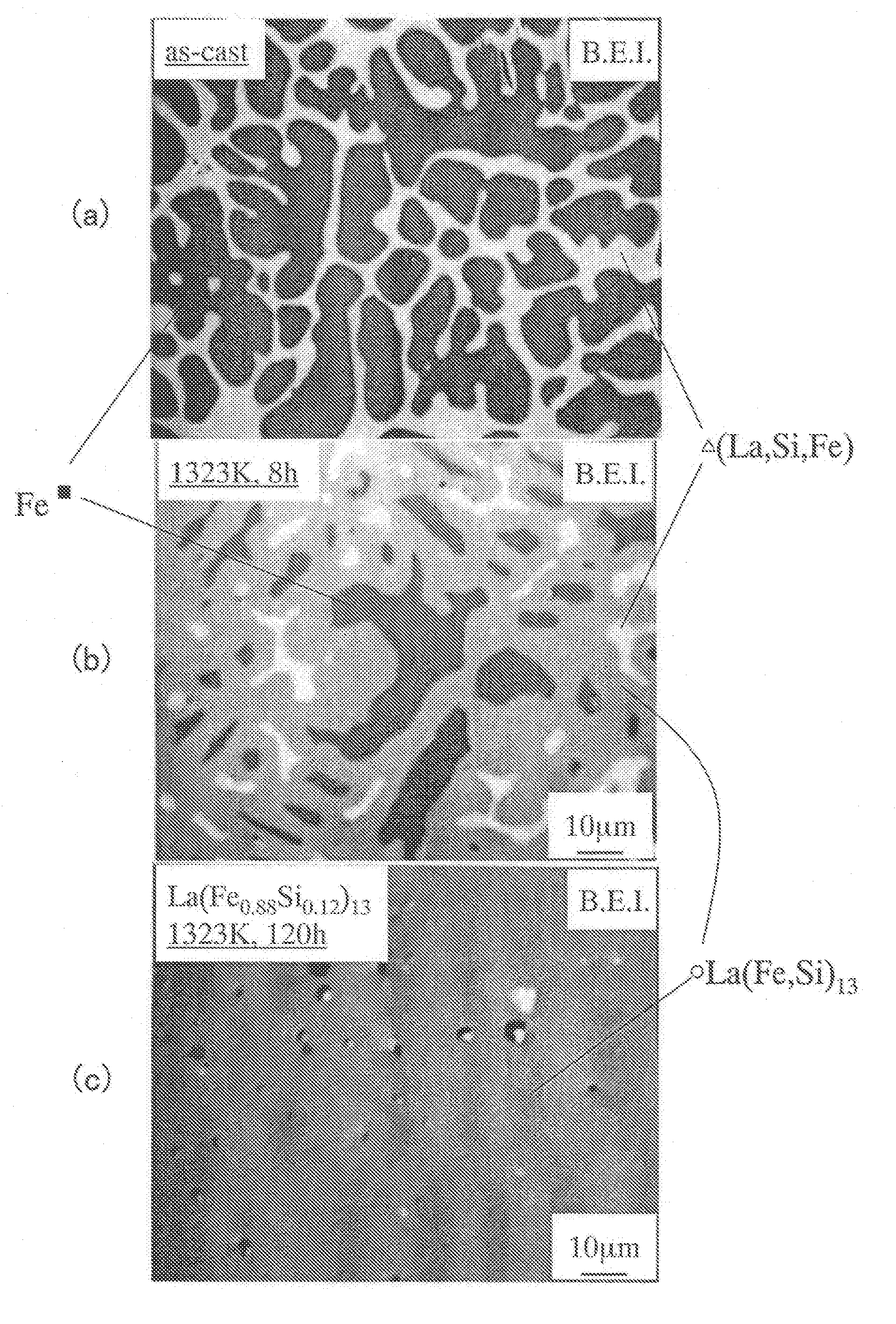
[0175] Rapidly solidified alloy ribbons having a composition La(Fe0.88Si0.12)13 were made by a strip casting process at peripheral velocities of 5 m / s and 15 m / s of quenching roller, respectively. The average thicknesses of the alloys were 150 μm with a standard deviation of 15 μm and 100 μm with a standard deviation of 10 μm, respectively. When their crystal structures were analyzed by the powder XRD and the SEM, the constituent phases thereof were an NaZn13-type La(Fe, Si)13 phase, a bcc-(Fe, Si) phase and an La-rich portion (phase) with a crystal structure which has not been identified. And the average minor-axis sizes of these phases were 1.5 μm and 1.1 μm, respectively. Each of these ribbons was coarsely pulverized with a power mill and then finely pulverized into a powder with a mean particle size of 6 μm using a jet mill in a nitrogen gas. Next, 0.05 mass % of zinc stearate and 0.1 mass % of wax were further added as a lubricant and as a binder, respectively, to ...

example no.2

Example No. 2

[0176] The present inventors analyzed what effects the differences in the alloy preparation process, composition and manufacturing process had on the sintering process. The results are as follows.

[0177]FIG. 24 shows locations of tested compositions on the ternary phase diagram of La—Fe—Si.

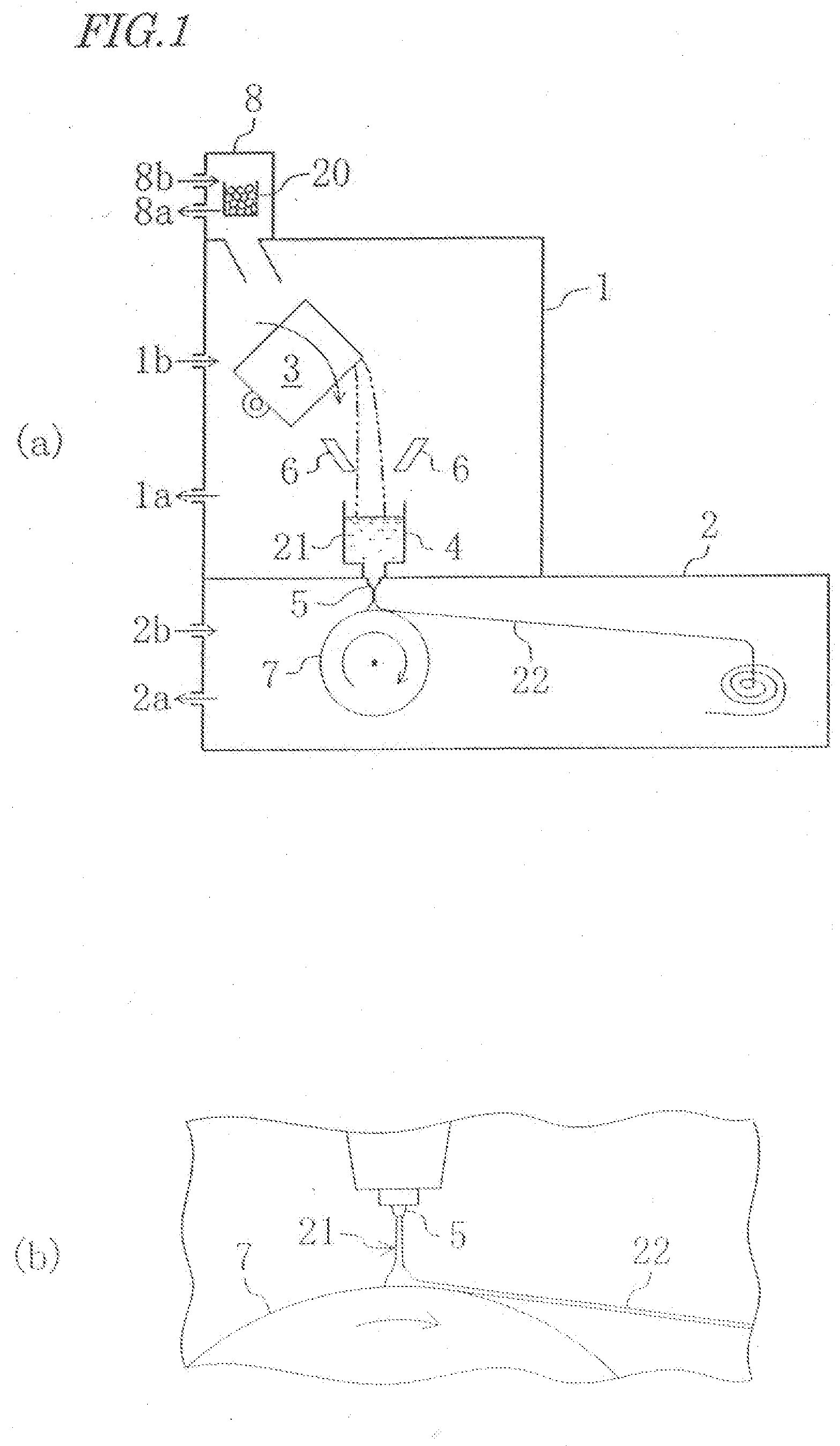
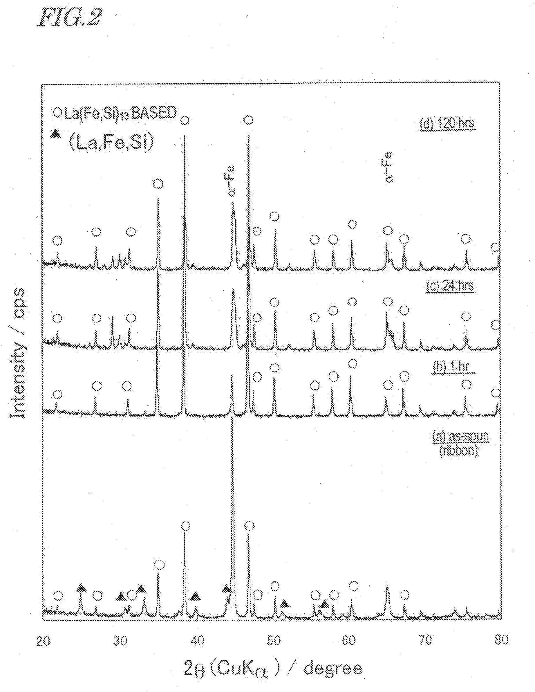
[0178] The manufacturing process was carried out as follows. Specifically, an as-cast alloy was made by a die casting process, pulverized, compacted and then sintered. Meanwhile, an as-spun alloy (rapidly solidified alloy ribbon), prepared by a melt spinning process (at 10 m / s), was pulverized, compacted, and sintered. And these two types of alloys were compared with each other. When the crystal structure of the as-spun alloy obtained by the melt spinning process was analyzed by the powder XRD and the SEM, the constituent phases thereof were an NaZn13-type La(Fe, Si)13 phase and a bcc-(Fe, Si) phase, which had average minor-axis sizes of 50 nm to 100 nm. To compare the structures of ...


PUM

PropertyMeasurementUnit
Temperatureaaaaaaaaaa

Abstract

A magnetic alloy material according to the present invention has a composition represented by Fe100-a-b-cREaAbCoc, where RE is a rare-earth element always including La, A is either Si or Al, 6 at %≦a≦11 at %, 8 at %≦b≦18 at %, and 0 at %≦c≦9 at %, and has either a two phase structure consisting essentially of an α-Fe phase and an (RE, Fe, A) phase including 30 at % to 90 at % of RE or a three phase structure consisting essentially of the α-Fe phase, the (RE, Fe, A) phase including 30 at % to 90 at % of RE and an RE(Fe, A)13 compound phase with an NaZn13-type crystal structure. The respective phases have an average minor-axis size of 40 nm to 2 μm.

Description

CROSS-REFERENCE TO RELATED PATENT APPLICATIONS [0001] This application claims the benefit of U.S. Provisional Application No. 60 / 667,801 filed Mar. 31, 2005, which is incorporated by reference.BACKGROUND OF THE INVENTION [0002] 1. Field of the Invention [0003] The present invention relates to a magnetic alloy material that can be used effectively as a magnetic refrigerant material or a magnetostrictive material and also relates to a method of making such a magnetic alloy material. [0004] 2. Description of the Related Art [0005] A magnetic alloy, having a composition represented by the general formula: La1-zREz(Fe1-xAx-y-TMy)13 (where A is at least one element that is selected from the group consisting of Al, Si, Ga, Ge and Sn; TM is at least one of the transition metal elements; RE is at least one of the rare-earth elements except La; and the mole fractions x, y and z satisfy 0.05≦x≦0.2, 0≦y≦0.1 and 0≦z≦0.1, respectively, and which will be referred to herein as an “La(Fe, Si)13 base...

Claims


Application Information

Patent Timeline
IPC IPC(8): H01F1/08
CPCH01F1/015
Inventor HIROSAWA, SATOSHITOMIZAWA, HIROYUKIKOGURE, RYOSUKE
Owner HITACHI METALS LTD
Why Eureka
Try Eureka